
Method and apparatus for reduced noise band switching circuits

a switching circuit and noise reduction technology, applied in the field of oscillators, can solve problems such as phase noise in the output of the vco

Inactive Publication Date: 2007-01-23
SIRIFIC WIRELESS CORP
View PDF7 Cites 2 Cited by
  • Summary
  • Abstract
  • Description
  • Claims
  • Application Information

AI Technical Summary

Benefits of technology

[0006]It is an object of the present invention to obviate or mitigate at least one disadvantage of previous voltage control oscillator circuits.
[0007]In a first aspect, the present invention provides a low-phase noise voltage control oscillator (VCO) comprising a voltage source for supplying a control voltage to the VCO core; a phase lock loop, having an output connected to an input of the voltage source; a VCO core, including an amplifier circuit and a tank circuit; having an output connected to an input of the phase lock loop; a capacitance divider circuit attenuator, located between the voltage source and the VCO core, for reducing noise from the voltage source to the VCO core to reduce frequency variation of the voltage source.
[0008]In a further embodiment, there is provided a method of reducing noise in a voltage control oscillator (VCO) comprising the steps of providing an attenuated voltage to a VCO core comprising an amplifier circuit and a tank circuit; and biasing the amplifier circuit via an amplifier bias including amplifier switches and the tank circuit via a tank bias including tank switches, to reduce noise in an output of the VCO core.

Problems solved by technology

In typical band switching circuits, biasing of the amplifier or a tank circuit introduces noise which results in phase noise being present in the output of the VCO.

Method used


Image

  • Method and apparatus for reduced noise band switching circuits
  • Method and apparatus for reduced noise band switching circuits
  • Method and apparatus for reduced noise band switching circuits

Examples


Embodiment Construction

[0022]Generally, the present invention provides a method and apparatus for reduced noise band switching circuits.

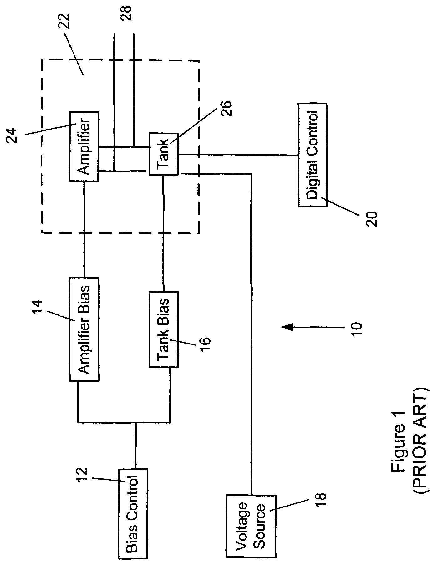
[0023]Turning to FIG. 1, a schematic diagram of a prior art voltage-controlled oscillator (VCO) is shown. The VCO 10 comprises a bias control 12 which is connected to an amplifier bias 14 and a tank bias 16. A voltage source 18 and a digital control 20, along with the amplifier bias 14 and tank bias 16, are connected to a VCO core 22. The VCO core 22 comprises an amplifier 24, and a tank 26. The outputs from the amplifier 24 and the tank 26 are transmitted as an output voltage 28.

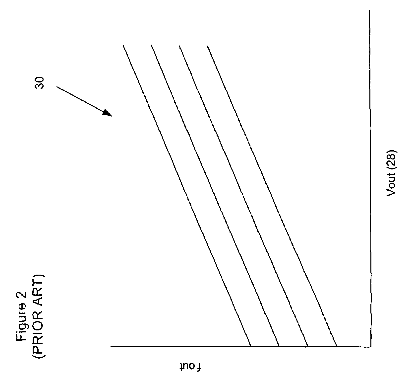
[0024]FIG. 2 provides a graph 30 of the output voltage 28 with respect to the frequency at which the VCO 10 is operating.

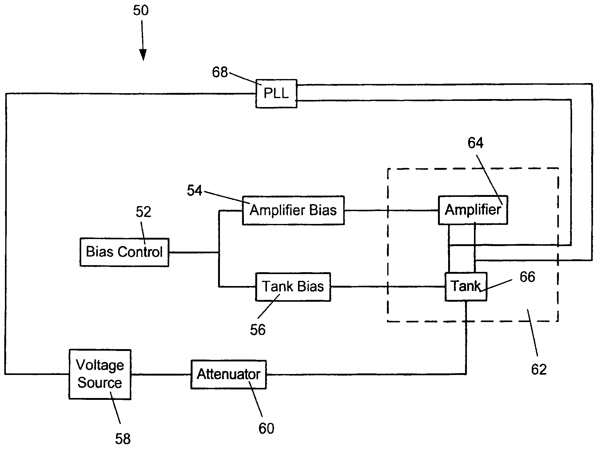
[0025]Turning now to FIG. 3, apparatus for a reduced noise band switching circuit is shown. The apparatus is directed at a VCO for signal generation in wireless radio frequency (RF) applications. The apparatus, or VCO, 50 comprises a bias control 52 connected to an amplifier bi...


PUM


Abstract

A low-phase noise voltage control oscillator (VCO) comprising a voltage source for supplying control voltage to the VCO core; a phase lock loop, having an output connected to an input of the voltage source; a VCO core, including an amplifier circuit with noiseless biasing and a tank circuit with noiseless biasing of the varactors; having an output connected to an input of the phase lock loop; and an attenuator, located between the voltage source and the VCO core, for reducing phase noise from the voltage source to the VCO core.

Description

CROSS REFERENCE TO RELATED APPLICATIONS[0001]This application claims the benefit of U.S. Provisional Application No. 60 / 531,609, filed Dec. 23, 2003, which is incorporated herein by reference.FIELD OF THE INVENTION[0002]The invention relates generally to the field of oscillators. More specifically, this invention relates to voltage controlled oscillators for signal generation in wireless communication applications.BACKGROUND OF THE INVENTION[0003]A voltage-controlled oscillator (VCO) is a circuit that produces an oscillating signal using amplification, feedback and a resonant circuit to generate a repeating voltage waveform, such that its output frequency is proportional to its input voltage.[0004]In wireless communication applications, VCOs operate over large frequency ranges. VCO's generally comprise a tank circuit and an amplifier circuit, operation of which will be well known. Biasing of such circuits is also known and described in U.S. Pat. No. 6,674,333 to Peckham et al, which...

Claims


Application Information

Patent Timeline
Patent Type & Authority Patents(United States)
IPC IPC(8): H03B5/00H03B5/04H03B5/12H03L7/099
CPCH03B5/04H03L7/099H03B5/1228H03B5/1293H03B5/124H03B5/1212H03B2200/0088H03L7/08
Inventor YAVORSKYY, VOLODYMYRMANKU, TAJINDERWEI, JAMES
Owner SIRIFIC WIRELESS CORP
Learn More