Electric rotating machine
a technology of rotating machines and rotating parts, which is applied in the direction of magnetic circuit rotating parts, magnetic circuit shape/form/construction, windings, etc., can solve the problems of enlarged risk of breakage of outgoing leads and difficulty in striking a good balance, and achieve the effect of simplifying the connection of outgoing leads and high productivity
- Summary
- Abstract
- Description
- Claims
- Application Information
AI Technical Summary
Benefits of technology
Problems solved by technology
Method used
Image
Examples
embodiment 1
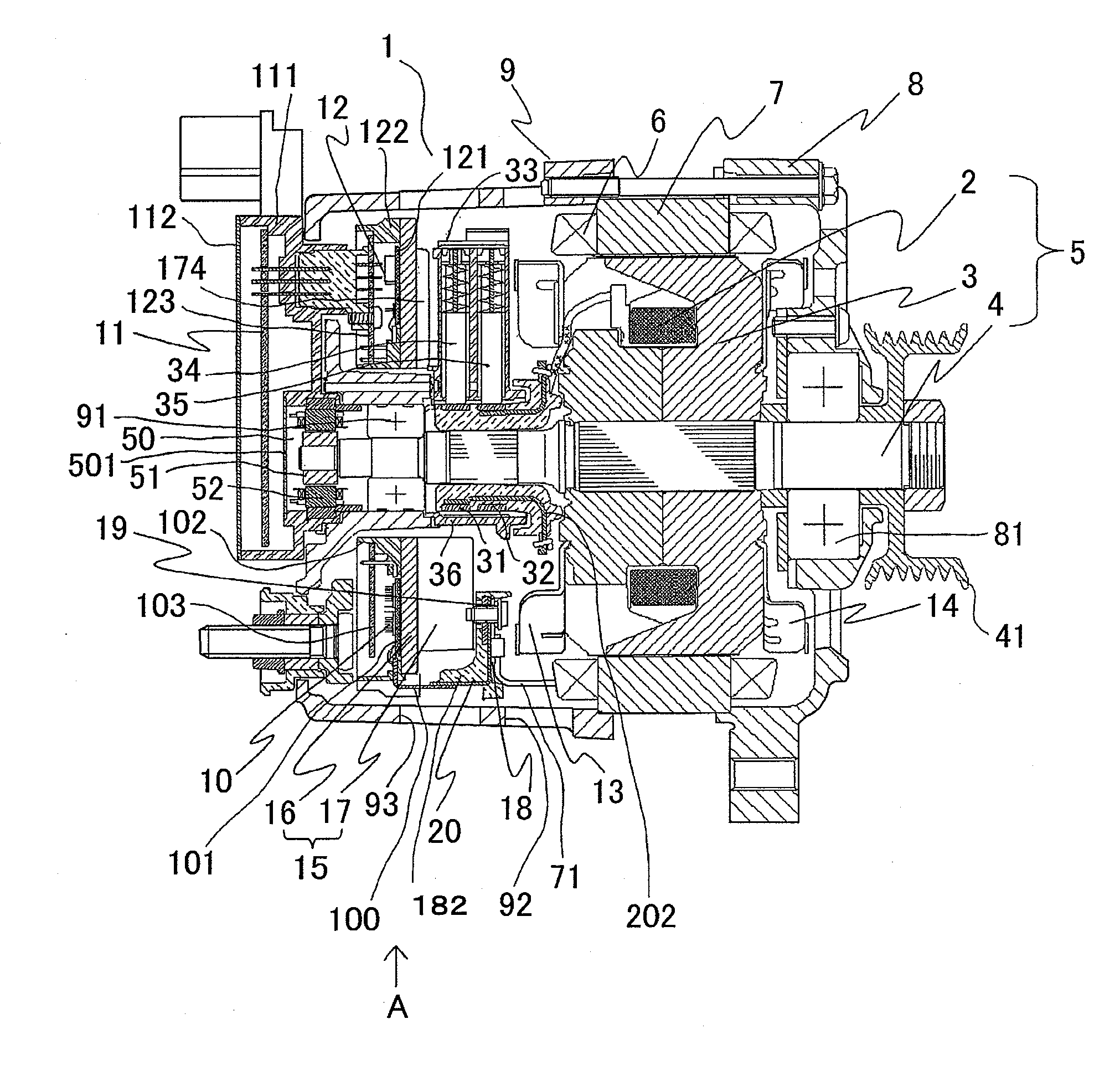
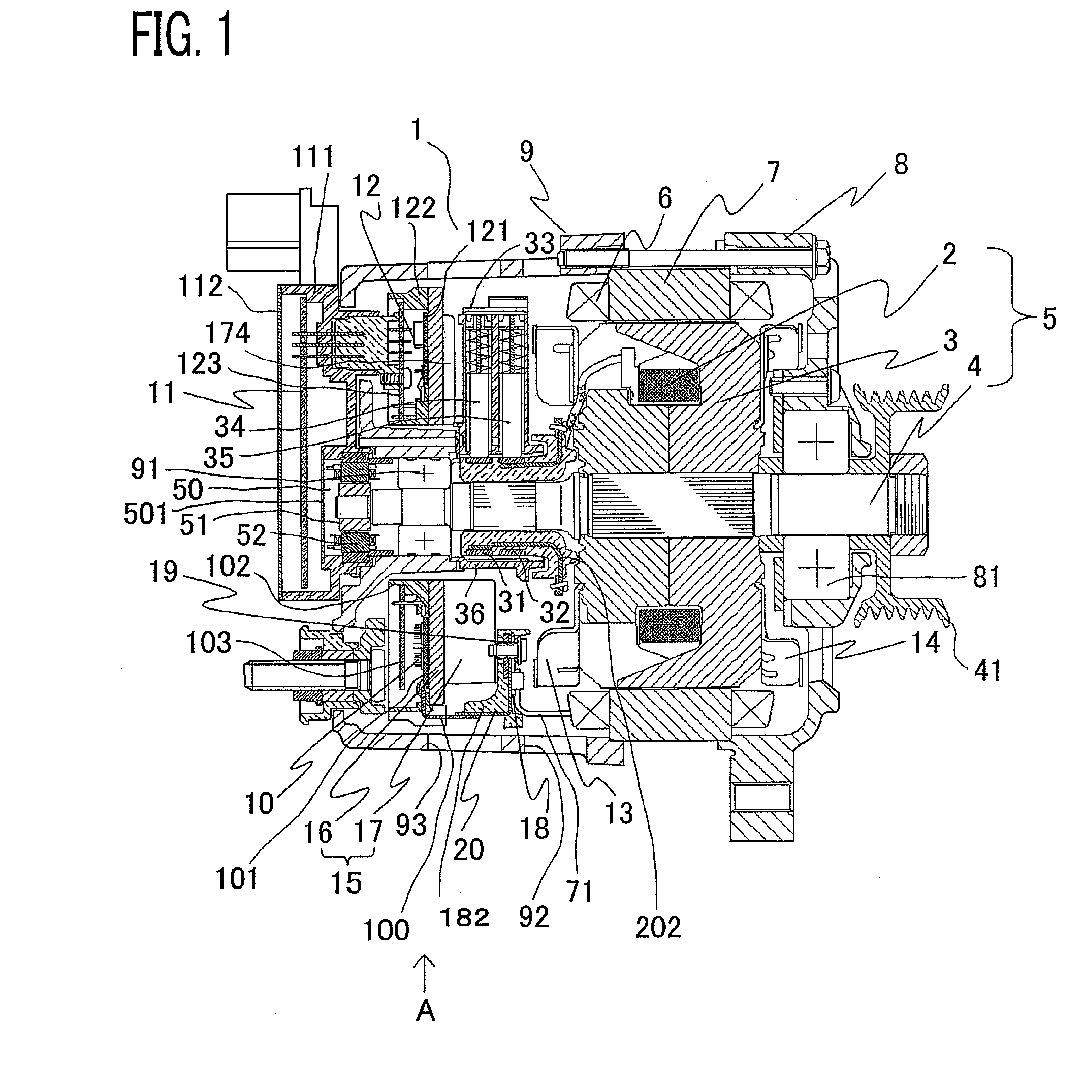
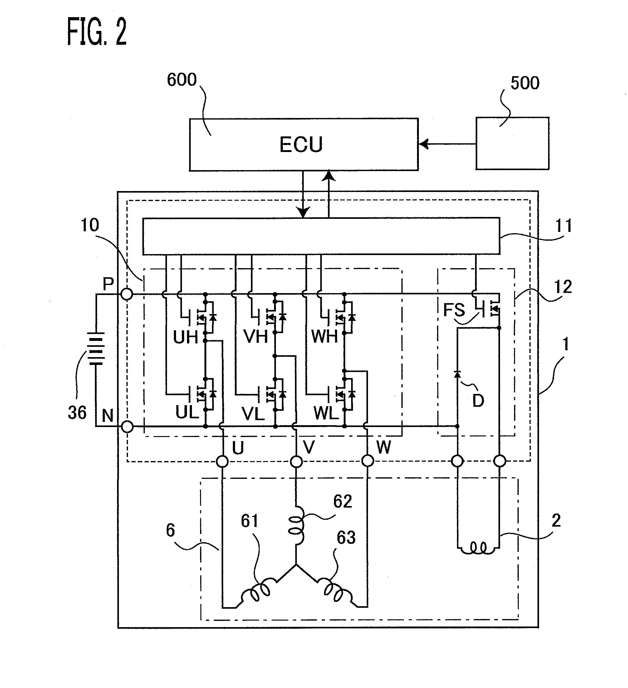
[0023]An in-vehicle electric rotating machine according to Embodiment 1 of the present invention will be explained below with reference to the accompanying drawings. FIG. 1 is a longitudinal cross-sectional view of an in-vehicle electric rotating machine according to Embodiment 1 of the present invention; FIG. 2 is an electric circuit diagram of an in-vehicle electric rotating machine according to Embodiment 1 of the present invention. In the following explanation, one side, of an in-vehicle electric rotating machine, at which a pulley to be coupled with the output axle of an engine is provided will be referred to as the “front-side”, and the other side opposite to the front-side will be referred to as the “rear-side”. In FIGS. 1 and 2, an in-vehicle electric rotating machine 1 is provided with a front-side housing 8, a rear-side housing 9, a rotor 5 whose shaft 4 is pivotably held by a front-side bearing 81 supported by the front-side housing 8 and a rear-side bearing 91 supported ...
embodiment 2
[0055]FIG. 6 is a side view of an intermediate plate and a heat sink according to Embodiment 2 of the present invention. In Embodiment 2, on an intermediate plate 18, there is provided a shielding wall 21 for preventing cooling air from flowing into a space where there is provided no cooling fin 17 of a heat sink 15, and integrally with the shielding wall 21, there is disposed a power circuit connection portion 20 for the connection with the outgoing leads from the power circuit unit 10.
[0056]In Embodiment 2 of the present invention, the power circuit unit 10 and the intermediate plate 18 are arranged in such a way as to flank the cooling fins 17; it is required to connect the power circuit connection portion 20 that connects the outgoing lead of the armature winding with the outgoing lead of the power circuit unit, in such a way as to cover a place where the cooling fins 17 are formed. However, due to a screw or the like for fixing the heat sink 15 in the electric rotating machine,...
embodiment 3
[0057]FIG. 7 is a cross-sectional view of principal parts of an electric rotating machine according to Embodiment 3. In Embodiment 3, in order to prevent exhausted cooling air from going toward an air inlet 93 in a rear-side housing 9, an exhausting guide 22 is formed in the peripheral portion of an intermediate plate 18. As a result, it can be prevented that air that has once passed through the electric rotating machine and has been warmed is absorbed again through the air inlet 93; therefore, cooling by the heat sink can effectively be performed.
PUM
 Abstract
Description
Claims
Application Information
 - R&D
- Intellectual Property
- Life Sciences
- Materials
- Tech Scout
- Unparalleled Data Quality
- Higher Quality Content
- 60% Fewer Hallucinations
Browse by: Latest US Patents, China's latest patents, Technical Efficacy Thesaurus, Application Domain, Technology Topic, Popular Technical Reports.
© 2025 PatSnap. All rights reserved.Legal|Privacy policy|Modern Slavery Act Transparency Statement|Sitemap|About US| Contact US: help@patsnap.com


