
Hydraulic Control Arrangement for the Screed of a Road Finisher

a control arrangement and hydraulic technology, applied in the direction of fluid couplings, roads, roads, etc., can solve the problems of affecting the uniform laying of road tops, and achieve the effect of improving laying quality and reducing loss

Active Publication Date: 2010-11-11
BOMAG
View PDF18 Cites 15 Cited by
  • Summary
  • Abstract
  • Description
  • Claims
  • Application Information

AI Technical Summary

Benefits of technology

[0005]Embodiments of the present invention advantageously avoid the drawbacks of conventional control or regulation of hydraulic actuating cylinders for screeds and of improving the laying quality. Furthermore, the activation should be efficient and involve as little loss as possible.
[0007]The term “loading pressure” refers in this case to that pressure which leads to lowering of the screed. Accordingly, the term “relief pressure” refers to that pressure which leads to raising of the screed. “Defined operating states” may differ as a function of the laying speed or speed of travel of the road finisher. The term “defined operating states” also includes starting or stopping processes. As stated at the outset, unexpected disturbances, for example ground unevenness, changes in temperature, etc. can occur on a construction site, thus impeding uniform laying of road topping. According to embodiments of the present invention, the work of the operator of the road finisher is facilitated in so far as he can define operating states or modes of operation so that the laying quality is kept constant despite external influences.
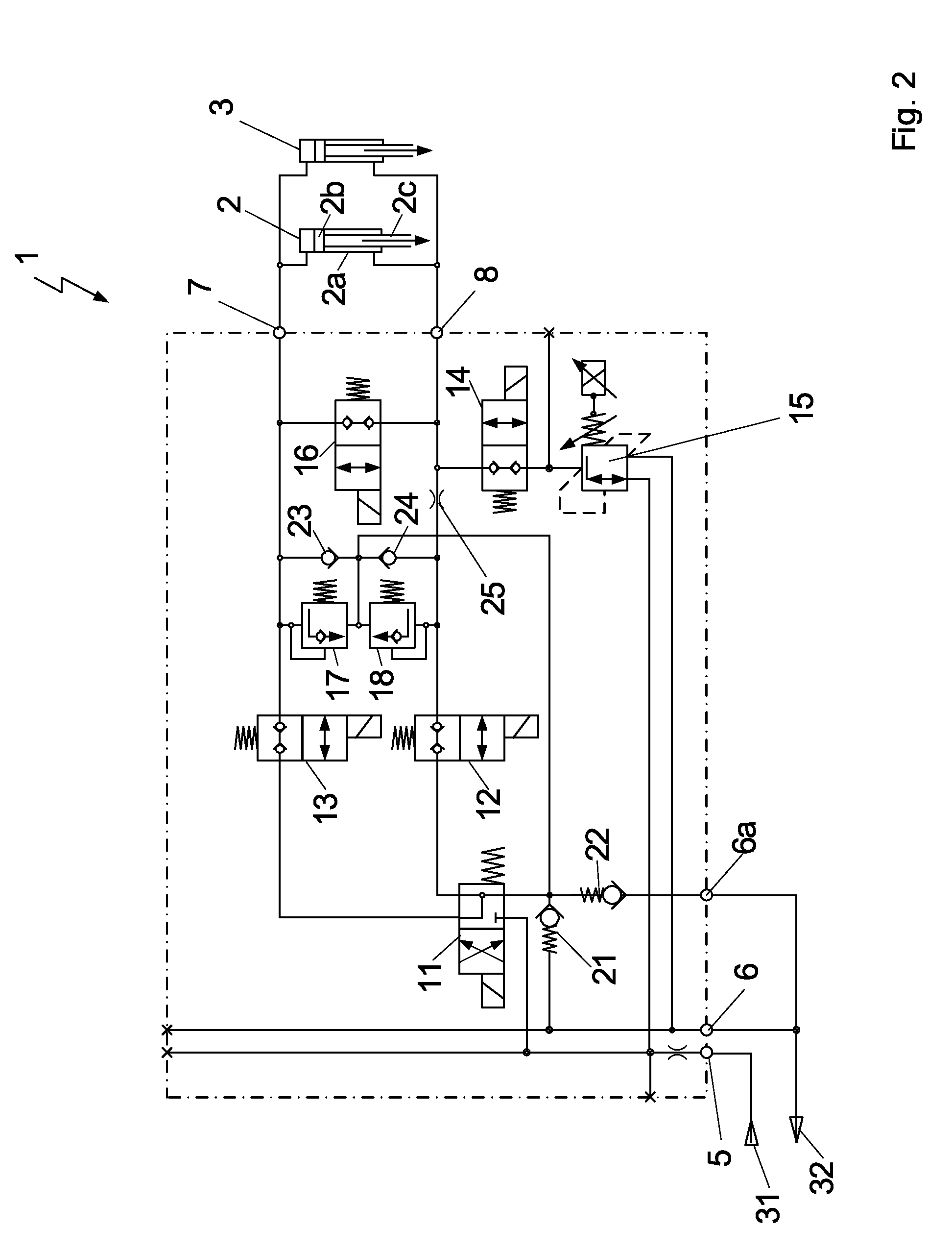
[0011]In an advantageous embodiment of the present invention, the hydraulic control arrangement has a double flow controller. A “double flow controller” comprises two flow controllers which are connected in parallel and are each provided, on account of check valves, only for one direction of flow. This double flow controller is preferably arranged in that line portion which is connected to the piston side of the hydraulic cylinder. The provision of the double flow controller allows uniform raising and lowering of the screed.
[0012]In a further preferred embodiment, the hydraulic control arrangement comprises a pressure sensor which is embodied to detect the piston-rod or piston side pressure, the loading pressure or relief pressure being controlled as a function of the detected piston-rod and / or piston side pressure. Two further parameters, namely the pressure on the housing or piston side and the pressure on the piston-rod side of the hydraulic cylinder, are thus available for controlling the loading or relief pressure of the screed. As the pressure sensors are arranged in direct proximity to the cylinder, it is possible to react rapidly and to set the desired values when required.
[0013]Preferably, the volumetric flow of hydraulic oil which is conducted to the hydraulic control arrangement via supply connection or the supply pressure being present at the supply connection is controllable in a low-loss way by a control pump. Thereby, it is possible to adjust a desired value of volumetric flow or pressure as needed instead of applying a constant volumetric flow or a constant pressure. For example, the pressure can exhibit a higher value when starting or stopping the road finisher than in the normal operation. Pre- and after-running control is possible.
[0015]Preferably, the volumetric flow of hydraulic oil which is conducted to the hydraulic control system via supply connection or the supply pressure being present at the supply connection is controllable in a low-loss way by a control pump. Thereby, it is possible to adjust a value of volumetric flow or pressure according to the needs instead of applying a constant volumetric flow or a constant pressure.

Problems solved by technology

As stated at the outset, unexpected disturbances, for example ground unevenness, changes in temperature, etc. can occur on a construction site, thus impeding uniform laying of road topping.

Method used


Image

  • Hydraulic Control Arrangement for the Screed of a Road Finisher
  • Hydraulic Control Arrangement for the Screed of a Road Finisher
  • Hydraulic Control Arrangement for the Screed of a Road Finisher

Examples


Embodiment Construction

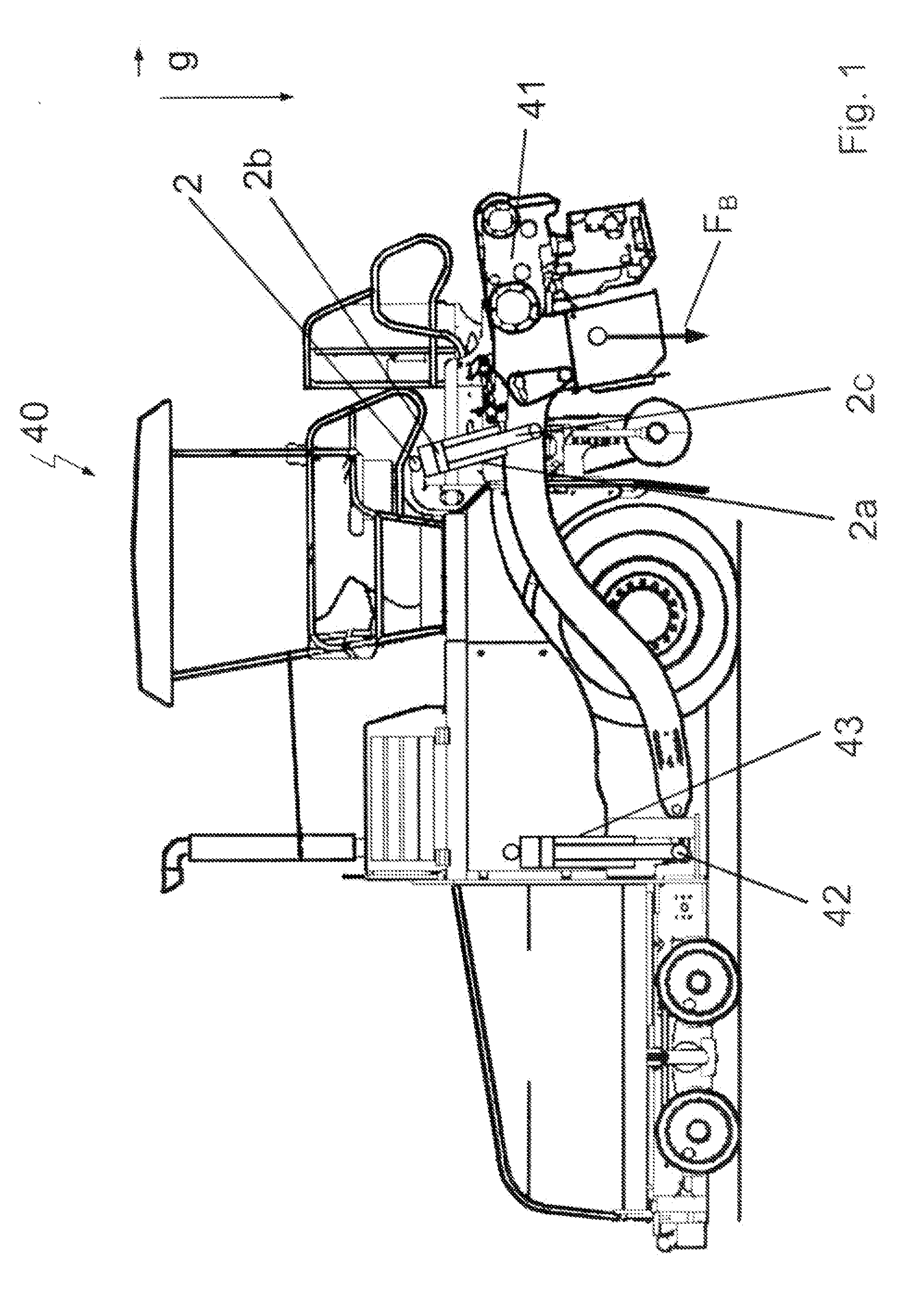
[0031]FIG. 1 is a side view of a road finisher 40 according to the invention. A screed 41 is articulated to the road finisher 40 at the point 42 and can be raised, lowered and held in any desired position with the aid of a double-acting actuating cylinder 2. The articulation point 42 itself is vertically adjustable via a leveling cylinder 43 in order to define the setting angle of the screed 41. This setting angle determines in combination with the speed of travel primarily the laying thickness. The actuating cylinder 2 is articulated on the piston side, i.e. with the cylinder housing 2a, to the chassis of the road finisher 40. On the piston-rod side, the actuating cylinder 2 is articulated to the screed 41. The screed 41 generates, on account of its dead weight, the weight force FB which is directed perpendicularly downward. In the position shown, the road finisher 40 is en route to the site of use, so that no force is directly exerted by the screed 41 onto the substrate.

[0032]FIG....


PUM


Abstract

A hydraulic control arrangement for activating a double-acting actuating cylinder, which is connected on the piston side to a road finisher and on the piston-rod side to a screed of the road finisher, is provided. The hydraulic control arrangement includes a supply connection, a tank connection and two consumer connections, in which a loading pressure or a relief pressure is applied to the piston of the actuating cylinder via the consumer connections. The loading pressure or relief pressure is controlled as a function of a defined operating state, and, in a controlling-the-screed-load operating state, the relief pressure supplied to the actuating cylinder on the piston-rod side is controlled via a proportional pressure control valve.

Description

CROSS-REFERENCE TO RELATED APPLICATIONS[0001]This application claims priority from foreign Patent Application Nos. DE 10 2009 012 384.9, filed on Mar. 9, 2009, and DE 10 2009 019 839.3, filed on May 4, 2009, the disclosures of which are incorporated herein by reference in their entirety.FIELD OF THE INVENTION[0002]The present invention relates to a hydraulic control arrangement and a control system for a screed of a road finisher. The invention further relates to a road finisher equipped with a hydraulic control arrangement or a control system.BACKGROUND OF THE INVENTION[0003]In conventional road finishers with floating screeds, the screed, which is articulated to the chassis of the road carrier and is drawn thereby, is held in a desired position or moved, so that defined laying conditions are met, by means of hydraulic actuating cylinders which are connected on the piston side or housing side to the chassis of the road finisher and on the piston-rod side to the screed.[0004]In the ...

Claims


Application Information

Patent Timeline
Patent Type & Authority Applications(United States)
IPC IPC(8): E01C19/22F16D31/02
CPCE01C2301/14E01C19/48
Inventor CHRIST, HERMANNHAGEN, IRINA
Owner BOMAG
Learn More