
Reference voltage circuits and on-die termination circuits, methods for updating the same, and methods for tracking supply, temperature, and/or process variation

Active Publication Date: 2010-11-11
MICRON TECH INC
View PDF25 Cites 13 Cited by
  • Summary
  • Abstract
  • Description
  • Claims
  • Application Information

AI Technical Summary

Problems solved by technology

However, variations in supply level and temperature will cause all of these parameters, OCD impedance, ODT impedance, and Vref level to fluctuate or drift with distinct behaviors.

Method used


Image

  • Reference voltage circuits and on-die termination circuits, methods for updating the same, and methods for tracking supply, temperature, and/or process variation
  • Reference voltage circuits and on-die termination circuits, methods for updating the same, and methods for tracking supply, temperature, and/or process variation
  • Reference voltage circuits and on-die termination circuits, methods for updating the same, and methods for tracking supply, temperature, and/or process variation

Examples


Embodiment Construction

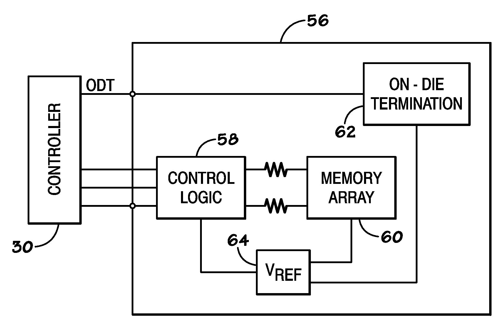
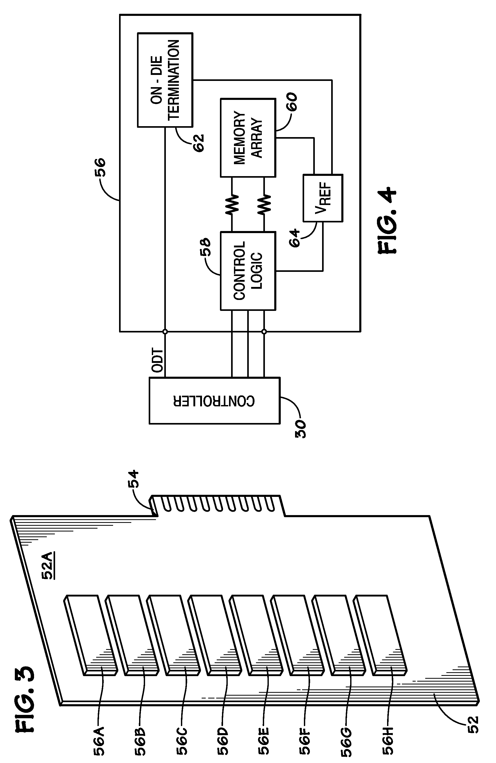
[0015]As discussed in further detail below, embodiments of the present invention include a reference voltage (Vref) circuit that has substantially similar paths and impedances as an on-die termination (ODT) circuit. More specifically, the similarity enables the Vref circuit impedances to track supply variations and temperature changes in a similar manner as the ODT circuit impedances. Further, in some embodiments an update scheme is provided for the ODT circuit and the Vref circuit to enable the simultaneous update of both circuits, thus minimizing discontinuities that would otherwise negatively impact data transmission and data capture.

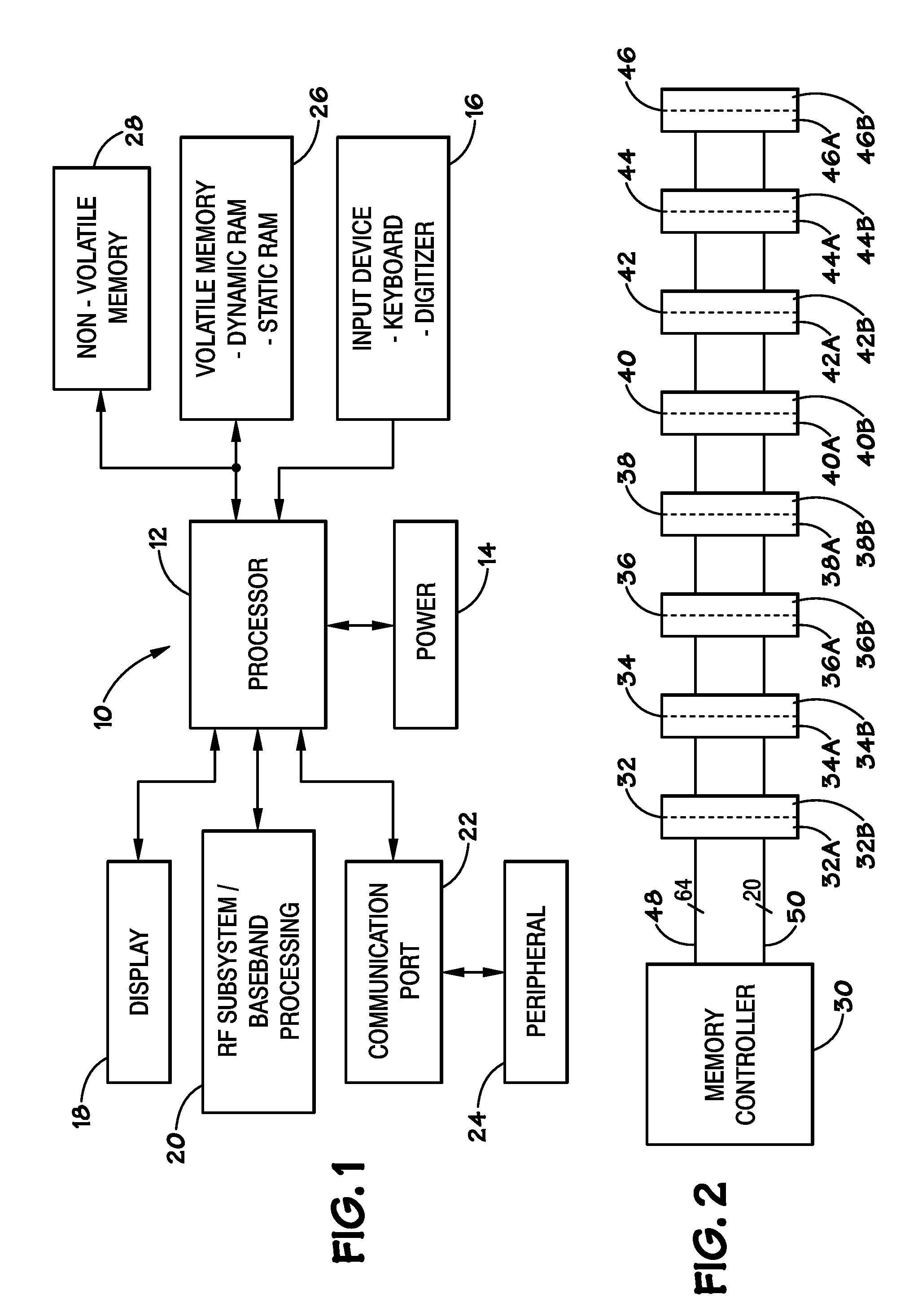
[0016]Turning now to the figures, FIG. 1 is a block diagram that depicts a processor-based system, generally designated by reference numeral 10. The system 10 may be any of a variety of types such as a computer, pager, cellular phone, personal organizer, control circuit, etc. In a typical processor-based system, one or more processors 12, such as a m...


PUM


Abstract

Devices and methods for operating devices are provided, such as those that include a memory device having a reference voltage (Vref) circuit that has substantially similar paths and impedances as an on-die termination (ODT) circuit. One such Vref circuit tracks supply variations and temperature changes in a manner substantially similar to the ODT circuit. In some embodiments an update scheme is provide for the ODT circuit and the Vref circuit to enable simultaneous update of each circuit through the same digital codes.

Description

BACKGROUND[0001]1. Field of Invention[0002]One or more embodiments of the invention relate generally to the field of digital communications and more particularly, to techniques for generating and adjusting reference voltages and impedances.[0003]2. Description of Related Art[0004]Processing speeds, system flexibility, and size constraints are typically considered by design engineers tasked with developing computer systems and system components. Computer systems generally include a plurality of memory devices which may be used to store programs and data and which may be accessible to other system components such as processors or peripheral devices. The memory devices, typically, are grouped together to form memory modules such as dual-inline memory modules (DIMMs). Further, computer systems may incorporate numerous memory modules to increase the storage capacity of the system.[0005]Generally, each memory device of a memory module includes one or more off-chip drivers (OCDs) for drivi...

Claims


Application Information

Patent Timeline
IPC IPC(8): H03K17/16H03K19/0175
CPCH03K19/0005H04L25/0298H04L25/0278H03K19/00384
Inventor HOLLIS, TIMOTHY M.
Owner MICRON TECH INC
Learn More