Rotary knife

a rotary knife and rotary blade technology, applied in the field of rotary blades, can solve the problems of over-processing of meat, and reducing the efficiency of the food processor, so as to improve the flow of meat, reduce the number, and simple and efficient

Inactive Publication Date: 2010-11-11
COMBICUT
View PDF21 Cites 10 Cited by
  • Summary
  • Abstract
  • Description
  • Claims
  • Application Information

AI Technical Summary

Benefits of technology

[0019]In use, the rotary knife of the first aspect provides the advantage of reducing friction and resistance generated by the rotational motion of the knife against adjacent discs. This is achieved because there are fewer blades disposed on the first side of the knife than in a conventional rotary knife which has the same number of blades on each side. In addition, the rotary knife of the first aspect provides the advantage of avoiding over-processing of the product because, compared to prior art knives, the meat is cut up less finely on the first side of the knife due to the fewer number of blades disposed on the first side of the knife.
[0023]Advantageously, each arm of the rotary knife carries a respective blade on the second side of the knife. This is a simple and efficient way of ensuring that there are sufficient blades on the second side of the knife such that a reduced number may easily be provided on the first side of the knife.
[0024]Advantageously, each arm of the rotary knife comprises respective channels extending across a surface of the arm in a direction substantially parallel to the axis of rotation. The channels provide the added advantage of improving the flow of meat from the first side of the knife to the second side of the knife. Advantageously, a depth of the channels is approximately half of a circumferential dimension of the arms. Advantageously, a depth of the channels varies along the length of the channels. More advantageously, the depth of the channels decreases towards the centre of the channels. Advantageously, a width of the channels varies along the length of the channels. More advantageously, the width of the channels decreases towards the centre of the channels. Advantageously, the channels are arcuate in cross-section. More advantageously, the channels are approximately semi-circular in cross-section. Advantageously, the channels on each arm are radially offset from the channels on adjacent arms.
[0025]Advantageously, each arm may have a respective end that is free and a respective end that merges with the hub, each arm being arcuate between the respective free end and the respective hub end. This provides the added advantage of limiting the amount of meat that escapes via the free end of each arm during rotation of the knife. More advantageously, the arc of each arm is concave. More advantageously again, the arc is arranged such that in use the first end is forward of the second end with respect to a direction of rotation.
[0026]Advantageously, the central hub and the arms are integrally formed. This provides for ease of manufacture and structural rigidity.

Problems solved by technology

This friction reduces the efficiency of the food processor.
This reduces the efficiency of the food processor.
Knives similar to that shown in FIGS. 1a to 2 can lead to over-processing of the meat (i.e. meat which is cut up too finely).
Over-processed meat has the disadvantage that the binding proteins are separated to a greater extent than meat which is not over-processed.
Thus, over-processed meat does not bind together in the desired manner.

Method used


Image

  • Rotary knife
  • Rotary knife
  • Rotary knife

Examples


first embodiment

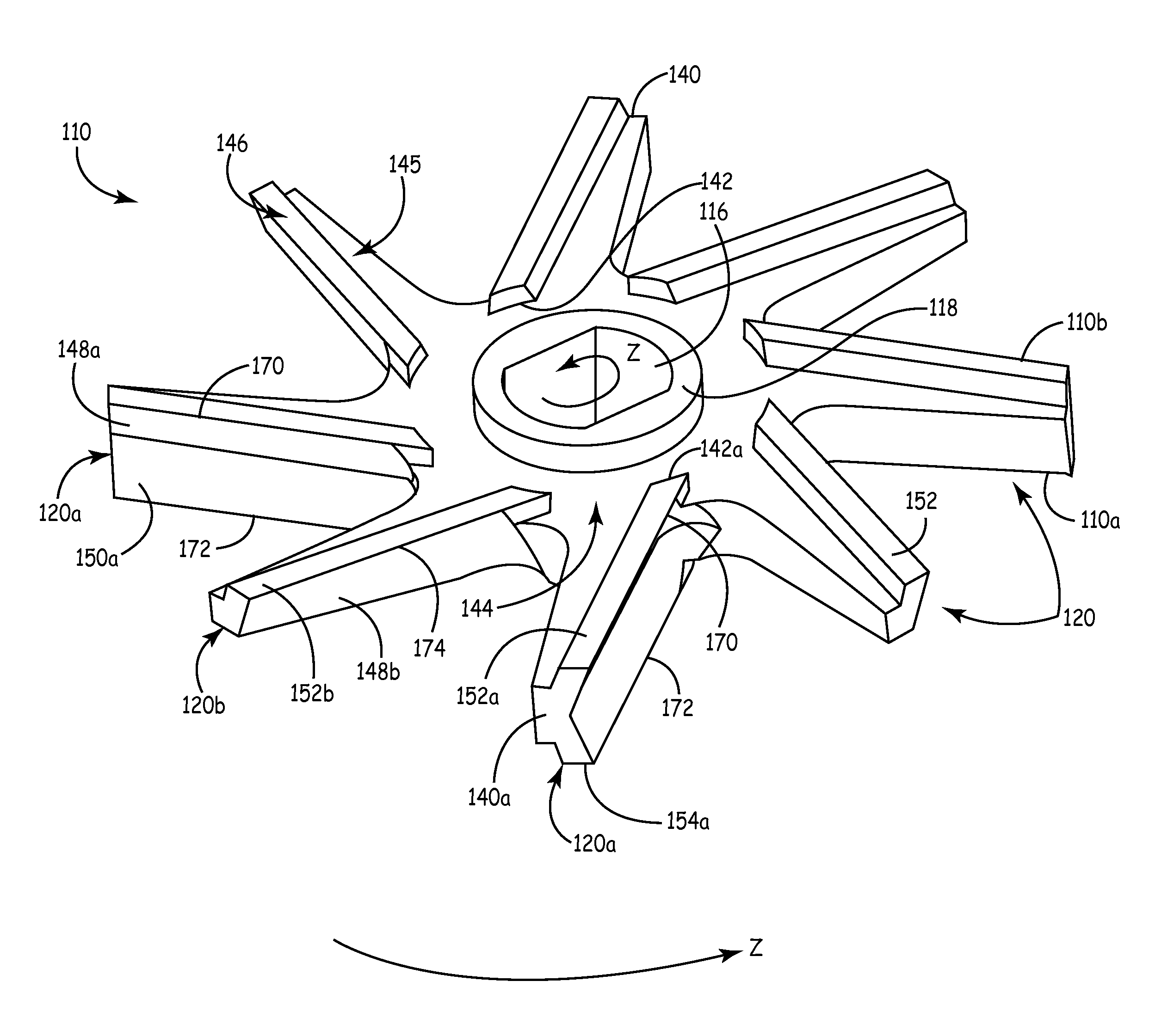
[0047]FIG. 3 is a perspective view of a rotary knife 110 according to a relatively simple first embodiment of the present invention. The knife 110 is adapted for use in a cutting apparatus such as an industrial food processor. Thus, a cutting apparatus according to one embodiment of the present invention is an industrial food processor comprising the knife 110 mounted coaxially between two perforated discs 112 and 114 as shown in FIGS. 5a and 5b. The discs 112 and 114 are fixed within a tubular housing (not shown). The knife 110 is rotatable about an axis of the food processor in a direction shown by arrow Z by means of a driveshaft (not shown). Food is fed through the food processor in the direction shown by arrow W. A diameter of the knife 110 is smaller than a diameter of the discs 112 and 114.

[0048]In an alternative embodiment, an industrial food processor may contain a further knife 110 and disc such that the configuration of components within the tubular housing comprises two ...

second embodiment

[0074]The rotary knife according to the present invention will now be described in use with reference to FIGS. 8a and 8b.

[0075]Meat is fed through the processor in the direction indicated by arrow W. As the meat exits the holes 234 in the exit surface 230 of the first disc 212, the blades 272 carried by the primary arms 220a of the knife 210 cut the meat as the knife 210 rotates. More specifically, the meat is cut by a scissor action between the edge of the blades 272 and the edges of the holes 234.

[0076]In use, the channels 256 assist in moving the meat efficiently from the exit surface 228 of the first disc 212 to the entry surface 230 of the second disc 214. Meat that has been cut as it emerged from the first disc 212 is channelled along the channels 256 towards the second disc 214. Thus, since the channels 256 are oriented substantially axially (i.e. parallel to the direction W), meat takes an efficient (i.e. short) route between the discs 212 and 214. As a result, meat moves m...


PUM


Abstract

There is described a rotary knife for use in a cutting apparatus. The rotary knife comprises a central hub, first and second sides of the knife, a plurality of arms, and a plurality of blades. The central hub defines an axis of rotation of the knife. The first and second sides of the knife are spaced apart in the axial direction. The plurality of arms extend outwardly from the hub. The plurality of blades are carried by the arms such that a number of blades disposed on the second side of the knife is greater than a number of blades disposed on the first side of the knife. There is also described a cutting apparatus comprising a rotary knife as described above.

Description

FIELD OF THE INVENTION[0001]The present invention relates to a rotary knife for use in a cutting apparatus such as an industrial food processor, and a cutting apparatus comprising such a knife.BACKGROUND OF THE INVENTION[0002]Conventionally, industrial food processors, such as meat grinders, are used to process meat into the consistency of sausage meat or burger meat, for example.[0003]As shown in prior art FIGS. 1a and 1b, an industrial food processor generally comprises a steel rotary knife 10 mounted coaxially between a first perforated disc 12 and a second perforated disc 14 that are also made of steel. The discs 12 and 14 are fixed within a tubular housing (not shown). The knife 10 is rotatable about an axis of the food processor. A diameter of the knife 10 is smaller than a diameter of the discs 12 and 14.[0004]The knife 10 comprises a central aperture 16, a hub 18, and eight arms 20 extending outwards from the hub 18. The central aperture 16 is adapted to receive a driveshaft...

Claims


Application Information

Patent Timeline
Patent Type & Authority Applications(United States)
IPC IPC(8): B02C18/00
CPCB26D1/29B02C18/362A22C17/00A22C17/0026A47J43/04B02C18/00B02C18/06B02C18/18B02C18/30B02C18/36
Inventor WALTERS, KEITH
Owner COMBICUT
Why Eureka
Try Eureka