
Medical system and method of switching antenna

a technology of switching antenna and medical system, which is applied in the direction of antenna feed intermediates, medical science, diagnostics, etc., can solve the problems of data not being accurately transmitted and received, transmission/receiving sensitivity deterioration,

Active Publication Date: 2010-11-04
OLYMPUS CORP
View PDF16 Cites 21 Cited by
  • Summary
  • Abstract
  • Description
  • Claims
  • Application Information

AI Technical Summary

Benefits of technology

[0012]A medical system according to an aspect of the present invention includes a capsule type medical apparatus that is introduced into a subject and includes a first antenna which outputs a radio wave having directionality in a first polarized wave direction and a first communication unit which executes a communication through the first antenna; an external antenna that is disposed outside of the subject and includes a second antenna having directionality to a second polarized wave direction and a third antenna that is disposed together with the second antenna and has directionality to a third polarized wave direction different from the second polarized wave direction of the second antenna; and an external machine that includes a selection unit which selects any of the second and third antennas and a second communication unit which executes a communication with the first communication unit through the external antenna whose polarized wave surface is selected by the selection unit.

Problems solved by technology

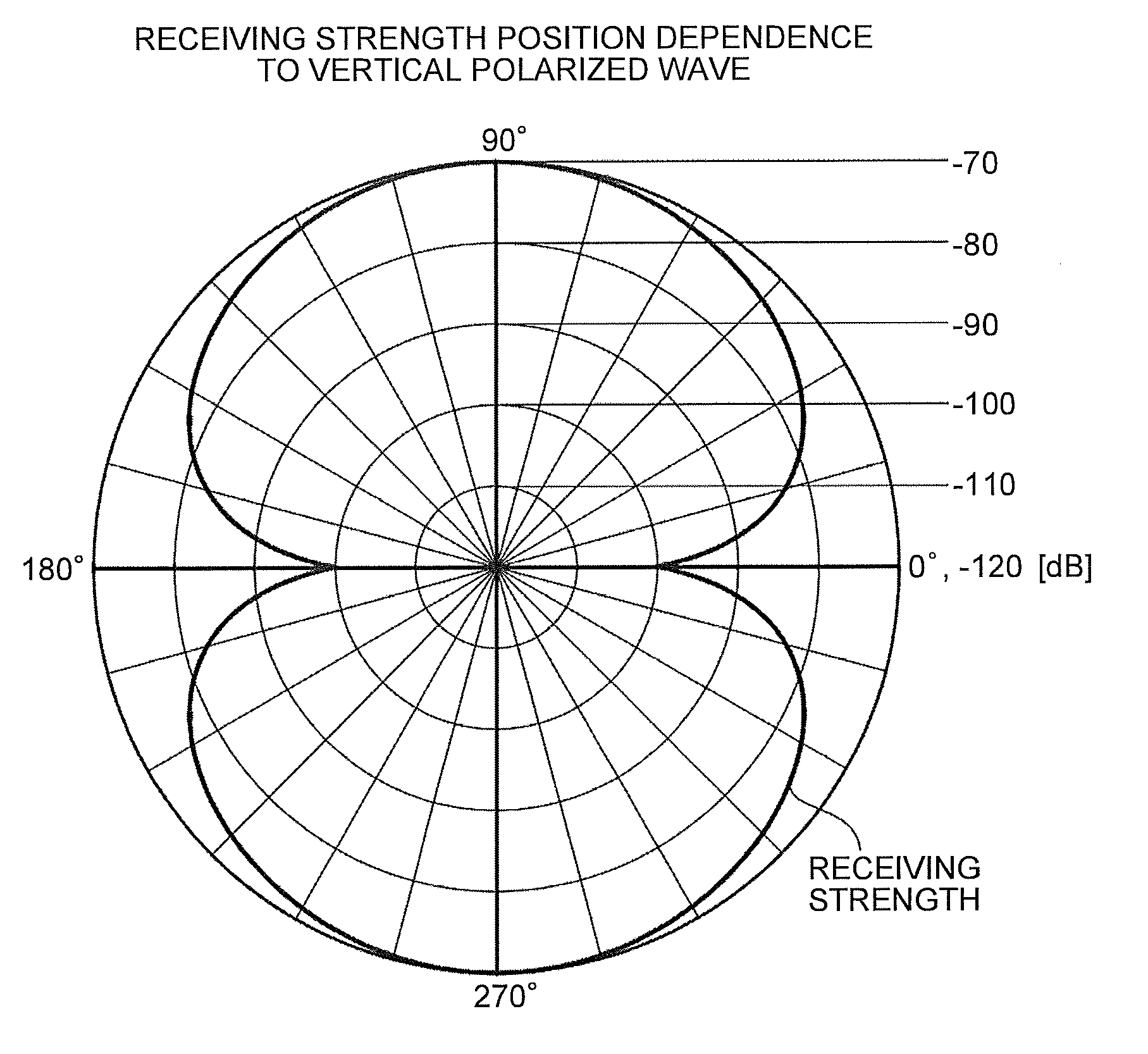
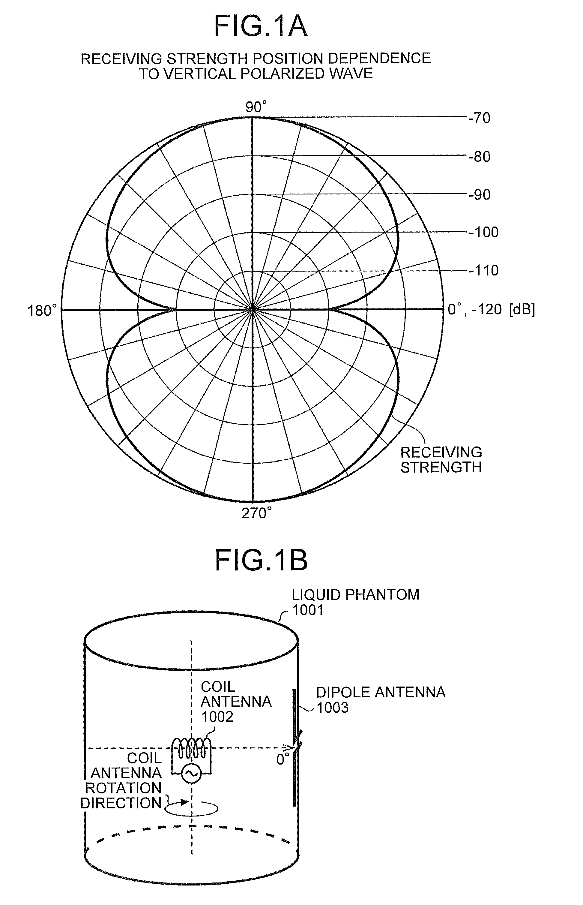
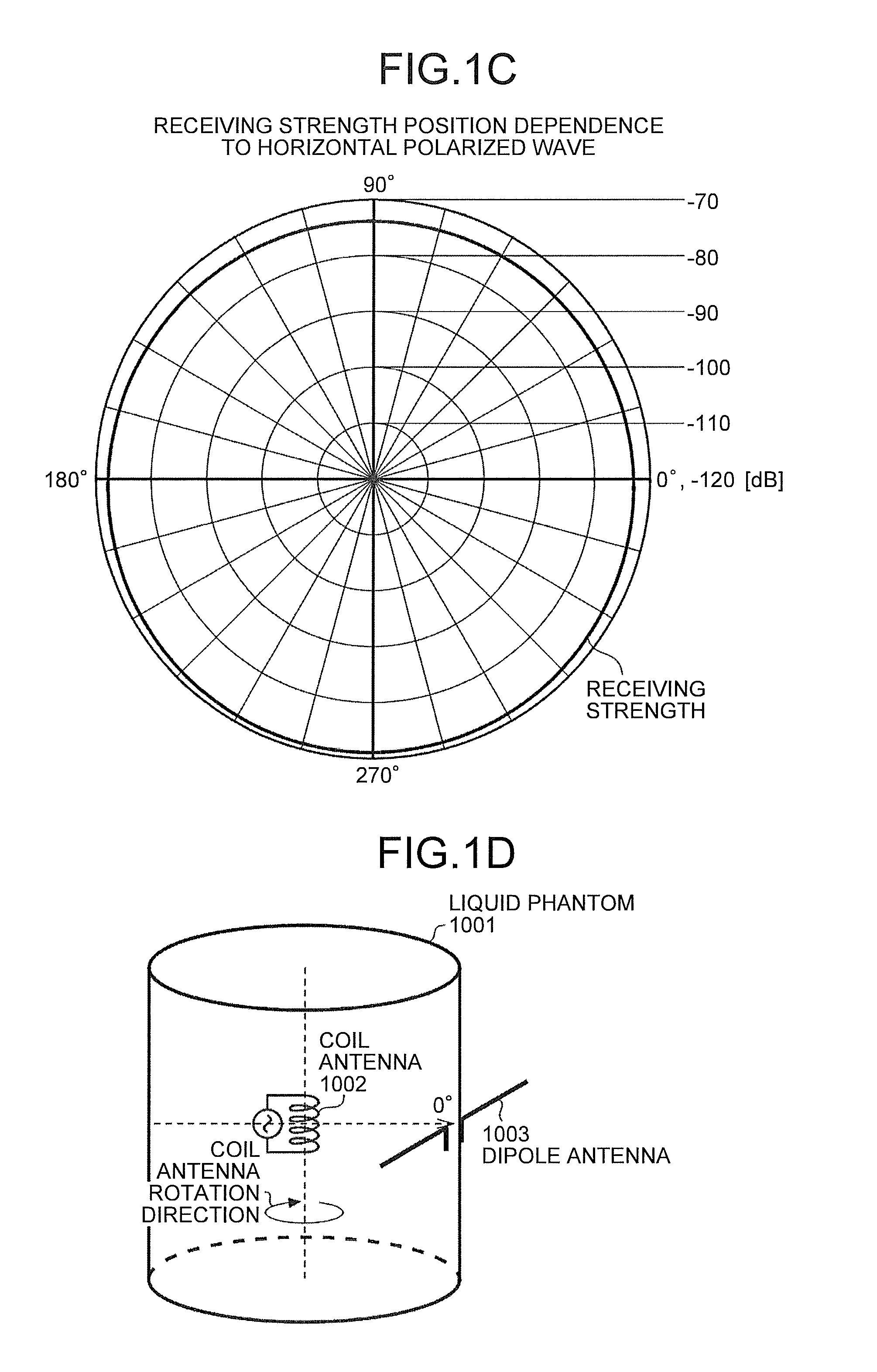
Accordingly, in a medical system, which uses a coil antenna as a transmission / receiving antenna of a capsule type medical apparatus and uses a dipole or loop antenna as a transmission / receiving antenna of an external machine as in a conventional medical system, the transmission / receiving sensitivity is deteriorated depending on a positional relation between the antenna of the capsule type medical apparatus and the antenna of the external machine and data may not be accurately transmitted and received between the capsule type medical apparatus and the external machine.

Method used


Image

  • Medical system and method of switching antenna
  • Medical system and method of switching antenna
  • Medical system and method of switching antenna

Examples


first embodiment

[0063]First, a configuration and an operation of a medical system 1 according to a first embodiment of the invention will be explained in detail with reference to the drawings. Note that the embodiment will be explained exemplifying a case that an inner wall image of a stomach 102 is obtained using a capsule type medical apparatus 10 which floats on a liquid 104 stored in the stomach 102. However, the invention is not limited to the case and can be applied also to a capsule type medical apparatus for obtaining some kind of information in a subject 100 while moving from an esophagus to an anus. Further, in-subject information obtained by the capsule type medical apparatus 10 is not limited to a captured image and may be various information such as an in vivo pH value, a cell tissue, a blood, a body fluid, and the like. Further, a body part in which the liquid 104 is stored is not limited to the stomach 102 and may be various organs, for example, a small intestine, a large intestine, ...

second embodiment

[0116]Next, a medical system 2 according to a second embodiment of the invention will be explained in detail with reference to the drawings. FIG. 9A is an upper view showing a schematic configuration of an external antenna 20B according to the embodiment. Further, FIG. 9B is a D-D′ sectional view of FIG. 9A, FIG. 9C is an E-E′ sectional view of FIG. 9A, and FIG. 9D is an F-F′ sectional view of FIG. 9A. Further, FIG. 10 is a schematic view showing a schematic configuration of the medical system 2 according to the embodiment. Note that, in FIG. 9A, the cover film 24 for protecting an antenna portion is omitted to clarify explanation.

[0117]As shown in FIG. 9A, the external antenna 20B includes a dipole antenna 21s disposed on an extending surface of a flexible board 23A obliquely to the two dipole antennas 21a and 21b of the external antenna 20 in addition to the dipole antennas 21a and 21b. The dipole antennas 21s include two elements 21sL and 21sR disposed symmetrically likewise the ...

third embodiment

[0122]Next, a medical system 3 according to a third embodiment of the invention will be explained in detail with reference to the drawings. FIG. 11 is a schematic view showing a schematic configuration of the medical system 3 according to the embodiment.

[0123]As shown in FIG. 11, in the medical system 3 according to the embodiment, two external antennas 20-1 and 20-2 are used. Further, the external machine 30 of the medical system 1 is replaced with an external machine 30C according to the configuration.

[0124]The individual external antennas 20-1 and 20-2 are the same as the external antenna 20 according to the first embodiment of the invention. However, in the embodiment, one external antenna 20-2 is bonded to the subject 100 so as to be oblique to the other the external antenna 20-1. That is, the dipole antenna 21a of the external antenna 20-1 tilts to the dipole antennas 21a and 21b of the external antenna 20-2, and the dipole antenna 21b of the external antenna 20-1 tilts to the...


PUM


Abstract

A medical system includes a capsule type medical apparatus introduced into a subject and having an antenna having directionality and a communication unit which executes a communication through the antenna, an external antenna, which is disposed outside of the subject and has an antenna having directionality and an antenna disposed together with the antenna and having directionality in a direction different from the antenna, and an external machine having a selection unit which selects any of the antennas in the external antenna and a second communication unit which executes a communication with the first communication unit through the antenna whose polarized wave surface is selected by the selection unit.

Description

CROSS-REFERENCE TO RELATED APPLICATIONS[0001]This application is a continuation of PCT international application Ser. No. PCT / JP2009 / 067711 filed on Oct. 13, 2009 which designates the United States, incorporated herein by reference.BACKGROUND OF INVENTION[0002]1. Field of the Invention[0003]The present invention relates to a medical system and an antenna switching method, and more particularly to a medical system and an antenna switching method in and by which a capsule type medical apparatus introduced into a subject such as a person, an animal, and the like executes a wireless communication with an external machine disposed outside of the subject.[0004]2. Description of the Related Art[0005]In, for example, a medical field, a swallow-type capsule type medical apparatus has conventionally existed which has an information acquisition function for obtaining various kinds of information in a subject by being introduced into the subject such as a person, an animal, and the like and a w...

Claims


Application Information

Patent Timeline
Patent Type & Authority Applications(United States)
IPC IPC(8): A61B5/07
CPCA61B1/00016A61B1/041A61B5/0013H01Q9/28H01Q21/24A61B5/6852
Inventor HOMAN, MASATOSHITAKENAKA, TOMOYA
Owner OLYMPUS CORP
Learn More