Method and apparatus for manufacturing carbon nanotube

a carbon nanotube and manufacturing method technology, applied in the field of carbon nanotube manufacturing, can solve the problems of increasing the manufacturing cost of carbon nanotubes, reducing the efficiency of raw material use, and most carbons being exhausted

Active Publication Date: 2010-11-04
DENSO CORP
View PDF3 Cites 29 Cited by
  • Summary
  • Abstract
  • Description
  • Claims
  • Application Information

AI Technical Summary

Benefits of technology

[0031]The method in the third aspect of the invention is also able to achieve the same advantageous effects as the method in the second aspect of the invention. Furthermore, in the method of the third aspect, merely by introducing the carrier gas (inert gas such as argon (Ar), helium (He) or Nitrogen (N2)) not containing the raw material gas (carbon source) into the reaction chamber, the reaction byproduct gas is expelled or exhausted from the reaction chamber and, hence, the catalyst and its surroundings are kept clean and free from reaction byproducts. The clean-up effect can be attained by merely switching the supply path from the raw material gas side to the carrier gas side without requiring linked opening and closing operations of two valves disposed immediately upstream of and downstream of the reaction chamber. The carrier gas used herein is required to reach the proximity of the catalyst through microscopic clearances between the adjacent vertically aligned carbon nanotubes. To meet the requirement, helium (He) is most preferable for its small molecular size.

Problems solved by technology

The conventional carbon nanotube manufacturing method and apparatus have a problem however as shown in FIG. 5 in that, even when the reaction time is extended to increase the film thickness of the synthesized carbon nanotubes (namely, for the purpose of increasing the length of the carbon nanotubes), the direct proportional relationship between the reaction time and the film thickness peaks out at a certain point of time.
Furthermore, continuing the supply of carbon source causes another problem in that most of the carbons are exhausted from the reaction tube before being used in the synthesis of carbon nanotubes.
This problem lowers the raw material use efficiency and increases the manufacturing cost of the carbon nanotubes.

Method used


Image

  • Method and apparatus for manufacturing carbon nanotube
  • Method and apparatus for manufacturing carbon nanotube
  • Method and apparatus for manufacturing carbon nanotube

Examples


embodiment 1

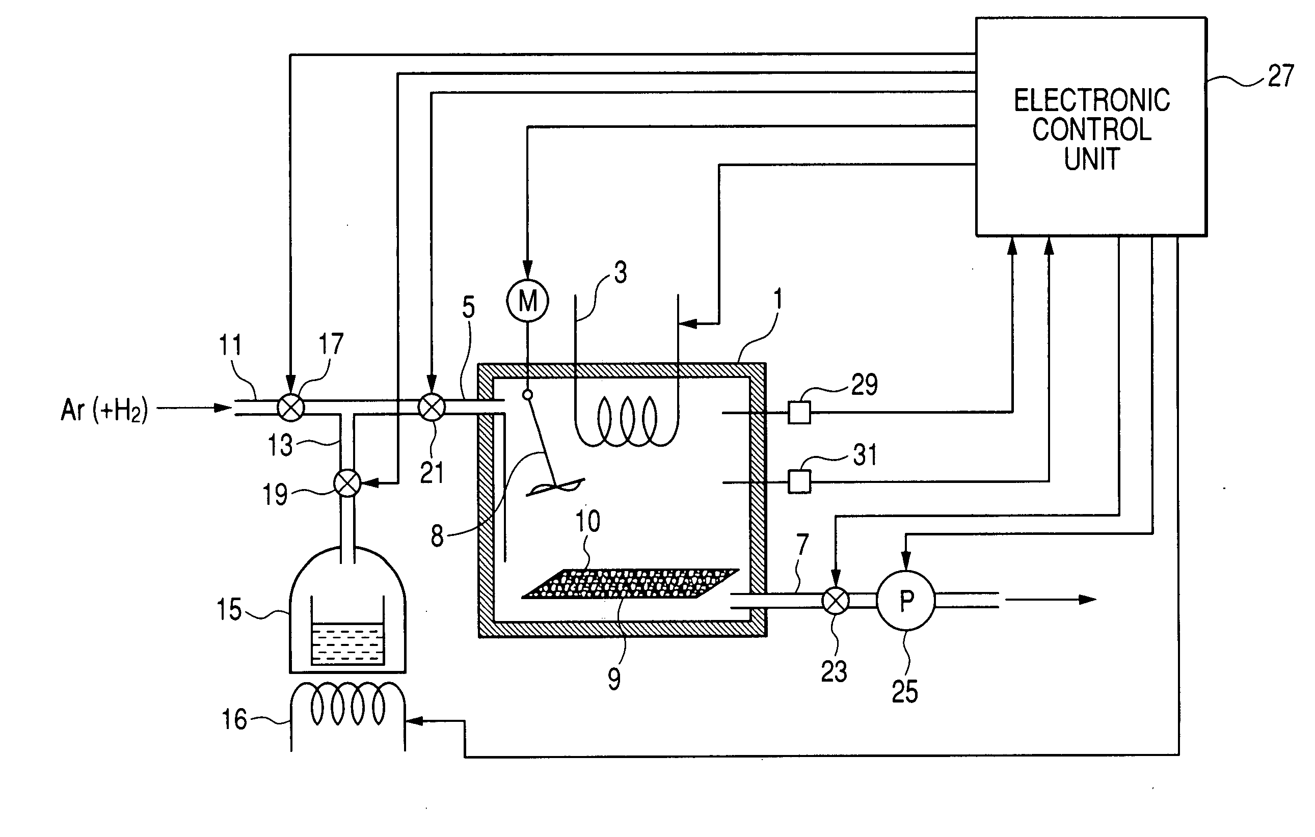
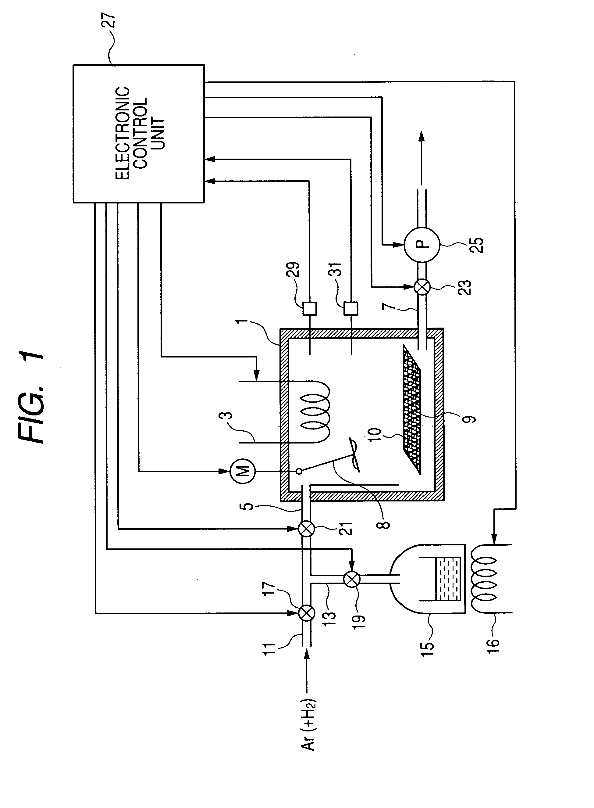
[0039]FIG. 1 shows in block diagram a carbon nanotube manufacturing apparatus according to a first embodiment (Embodiment 1) of the present invention. As shown in this figure, the manufacturing apparatus comprises a reaction chamber 1 in which a vertically aligned carbon nanotube is manufactured by using a chemical vapor deposition (CVD) method, a heater 3 for heating the interior of the reaction chamber 1, a supply path (pipe) 5 for supplying a raw material gas serving as a carbon source into the reaction chamber 1, and an exhaust path (pipe) 7 for exhausting gases including a reaction byproduct gas from the reaction chamber 1. A substrate 9 having a catalyst 10 carried thereon is placed in the reaction chamber 1. The substrate 9 is preferably made of quartz, and the catalyst 10 is preferably a CoMo catalyst. The catalyst 10 is fixed to a surface of the substrate 9. An electric fan 8 is disposed in the reaction chamber 1 for stirring a gaseous atmosphere in the reaction chamber 1.

[...

embodiment 2

[0077]A second embodiment (Embodiment 2) of the present invention will be described below with reference to FIG. 3. These parts which are similar to those described above with respect to the first embodiment (Embodiment 1) will not be described to avoid unnecessary duplication.

[0078]In Embodiment 2 a carbon nanotube manufacturing apparatus employs an annular furnace, such as used in the conventional apparatus shown in FIG. 4.

[0079]More specifically, as shown in FIG. 3, the carbon nanotube manufacturing apparatus comprises a tubular reaction chamber 32, a heater (annular furnace) 33, a supply path (pipe) 35, and an exhaust path (pipe) 37. A substrate 39 having a catalyst 40 carried thereon is placed in the tubular reaction chamber 32.

[0080]Connected to the supply pipe 35 are a first supply pipe 41 for supplying Ar as a carrier gas to the reaction chamber 32 via the supply pipe 35, and a second supply pipe 43 for supplying ethanol as a carbon source to the reaction chamber 32 via the ...

embodiment 3

[0086]Next, description will be made of a third embodiment (Embodiment 3) of the present invention. These parts which are similar to those described above with respect to the first and second embodiments (Embodiments 1 and 2) will be omitted from the description to avoid unnecessary duplication.

[0087]In each of Embodiments 1 and 2, the pressure sensor 31 or 59 for detecting the pressure in the reaction chamber 1 or 32 is used as a detecting means for detecting a condition in which the synthesis of carbon nanotubes has proceeded to a predetermined level. In Embodiment 3, however, the detecting means consists of a gas sensor, which is capable of monitoring a gaseous component in the reaction chamber 1 or 32 so as to determine whether the synthesis of carbon nanotubes has proceeded to the predetermined level.

[0088]More specifically, with the progress of a carbon nanotube synthesis operation, the concentration of a reaction byproduct (for example, CO2) increases. Accordingly, by monitor...


PUM

PropertyMeasurementUnit
Temperatureaaaaaaaaaa
Timeaaaaaaaaaa
Thicknessaaaaaaaaaa

Abstract

A carbon nanotube manufacturing method wherein a catalyst is heated in a reaction chamber while the reaction chamber is filled with argon gas containing hydrogen. When a predetermined temperature is reached in the reaction chamber, the reaction chamber is evacuated. Then a raw material gas as a carbon source is charged and sealed in the reaction chamber whereupon the synthesis of carbon nanotube begins. Subsequently, when a condition in which the synthesis of carbon nanotubes has proceeded to a predetermined level is detected, gases in the reaction chamber are exhausted. Then, the raw material gas is changed and sealed in the reaction tube again. Thereafter, the charging (synthesizing) operation and the exhausting operation are repeated until the carbon nanotube with a desired film thickness are synthesized. A carbon nanotube manufacturing apparatus is also disclosed

Description

CROSS REFERENCE TO RELATED APPLICATION[0001]The present application is based on and claims priority from Japanese Patent Application No. 2006-331952, filed Dec. 8, 2006, the content of which is incorporated herein by reference.BACKGROUND OF THE INVENTION[0002]1. Field of the Invention[0003]The present invention relates to the manufacture of a carbon nanotube and more particularly to a method of and apparatus for manufacturing a vertically aligned carbon nanotube grown by chemical vapor deposition (CVD) on a substrate.[0004]2. Description of the Related Art[0005]In the methods proposed heretofore, a substrate with a catalyst carried thereon is placed in a reaction tube disposed in an annular furnace, and while heating the catalyst, a raw material gas serving as a carbon source is continuously brought into contact with the heated catalyst to thereby synthesize a carbon nanotube grown on the substrate in vertical alignment (see Japanese Patent Laid-open Publication (JP-A) No. 2002-1802...

Claims


Application Information

Patent Timeline
IPC IPC(8): D01F9/12C23C16/26C23C16/52
CPCB82Y30/00C01B31/0206B82Y40/00Y10S977/843Y10S977/842C01B32/15
Inventor SUZUKI, YOSHINOBUMUKAINAKANO, SHINICHIOKEYUI, KENJIMORISHITA, TOSHIYUKIOOSHIMA, HISAYOSHI
Owner DENSO CORP
Why Eureka
Try Eureka