
System for regulating access to a resource

a resource and access control technology, applied in the field of system and method for regulating access to resources, can solve the problems of reducing the efficiency of managing access to resources and reducing the length of queues, and reducing the cost and complexity of the system, so as to improve the efficiency of the system and reduce the difficulty of queues

Active Publication Date: 2010-11-04
LO Q
View PDF4 Cites 74 Cited by
  • Summary
  • Abstract
  • Description
  • Claims
  • Application Information

AI Technical Summary

Benefits of technology

[0006]Unlike existing systems, this system does not require a communications network to inform a user as to whether they are able to access a resource, since the queue manager only sets a criterion and not a specific time for access to the resource. As the variable access parameter changes, the user is able to compare it with the access criterion and thereby determine whether they are able to access the resource. The cost and complexity of the system is therefore reduced.
[0040]With the increasing ubiquity of Internet-enabled mobile telephones, the portable module may be any communications device, but particularly a mobile telephone. Such a telephone, with reliable communications to a server such as a queue manager, allows the server to potentially have complete knowledge about the status of every user and every resource. In particular, the mobile telephone can be arranged to operate specific software to interface with the queue manager.

Problems solved by technology

Each attraction has a limited capacity for people to gain access to it at any specific time.
However, the most popular attractions tend to have longer queues for access than less popular attractions.
Moreover, potential users of an attraction may become bored queuing in a line.
Managing access to a resource efficiently whilst minimising the length of queue line is difficult.
Moreover, since the users are separated in two distinct groups, it is difficult to optimise allocation collectively for all users.

Method used


Image

  • System for regulating access to a resource
  • System for regulating access to a resource
  • System for regulating access to a resource

Examples


Embodiment Construction

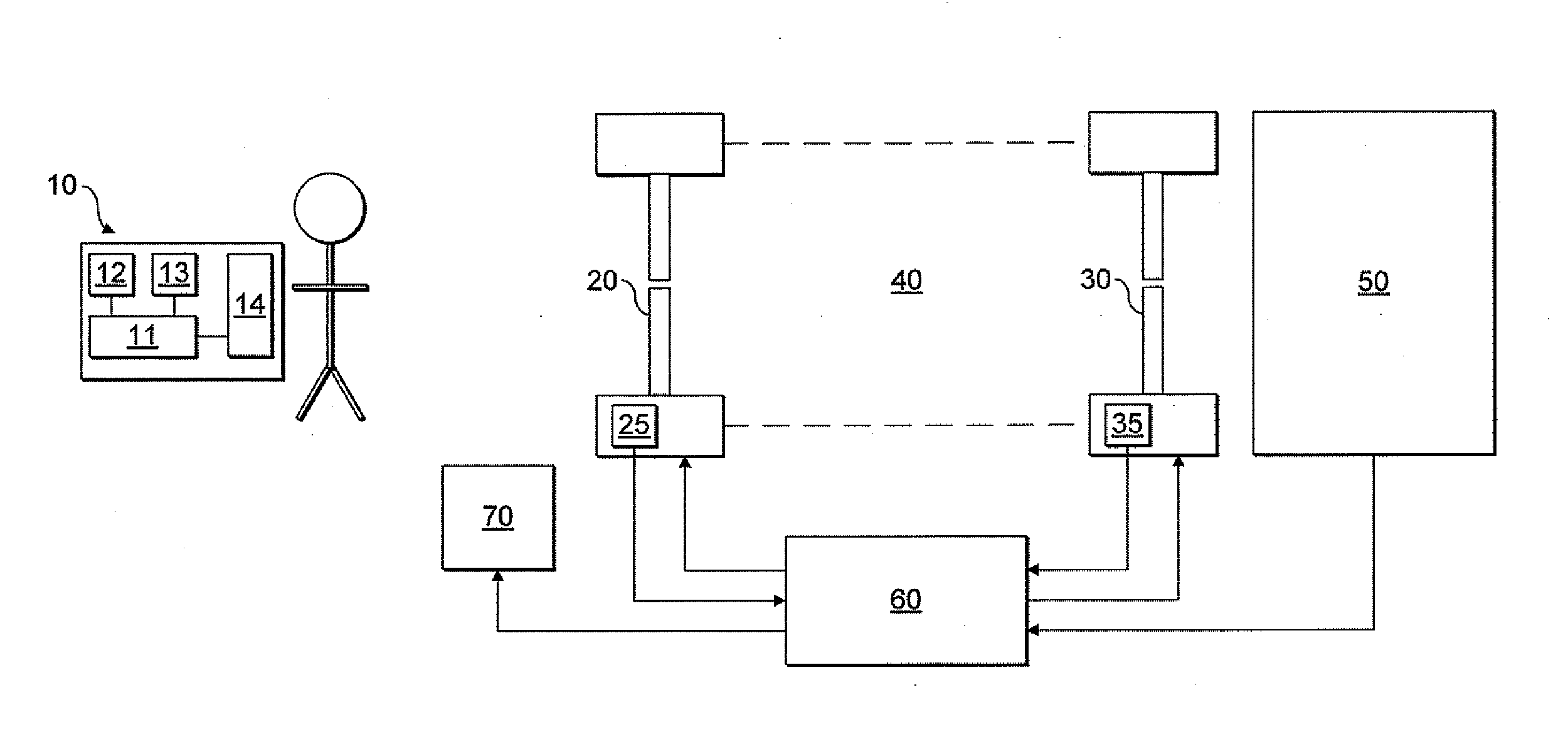
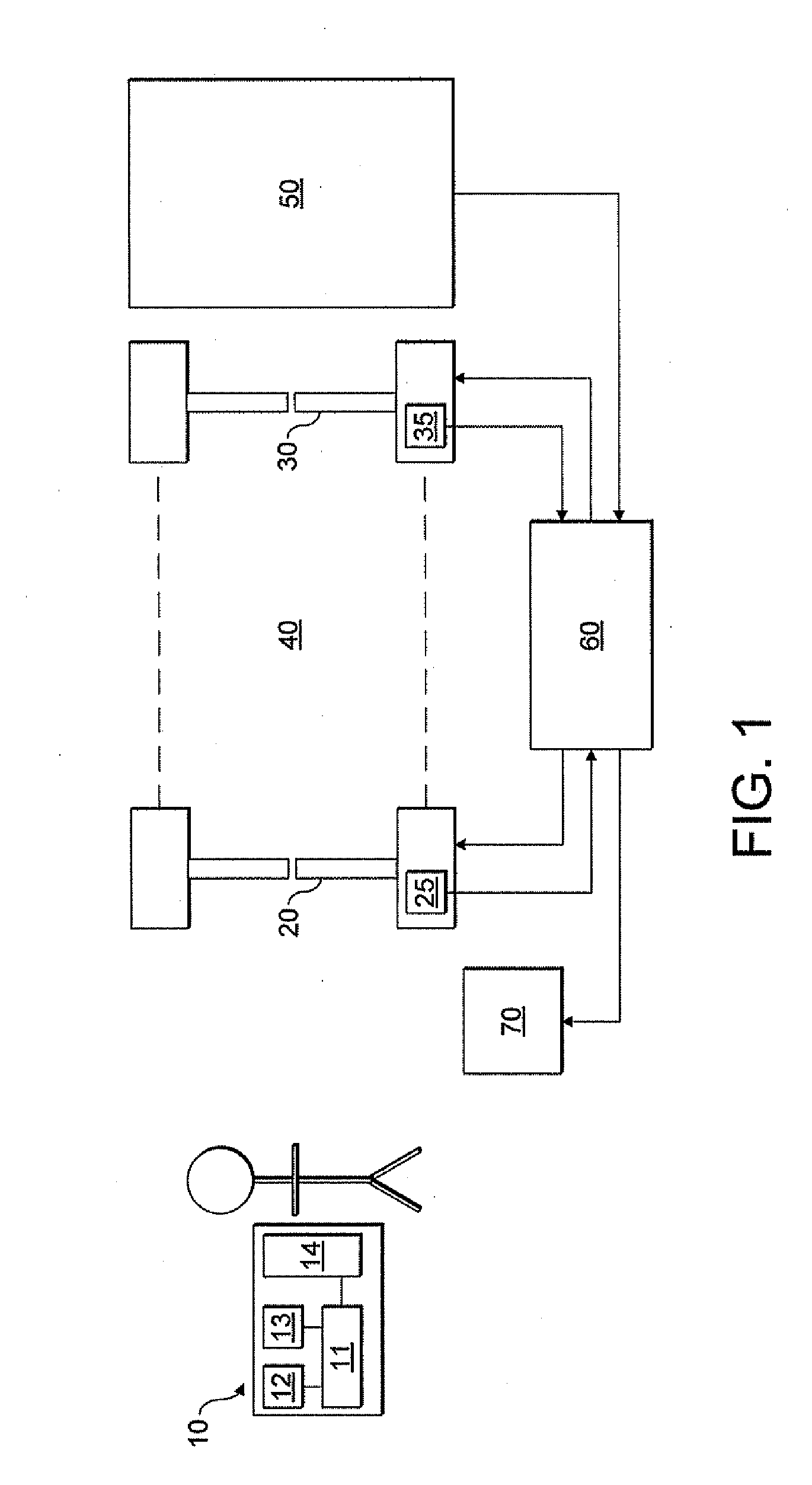
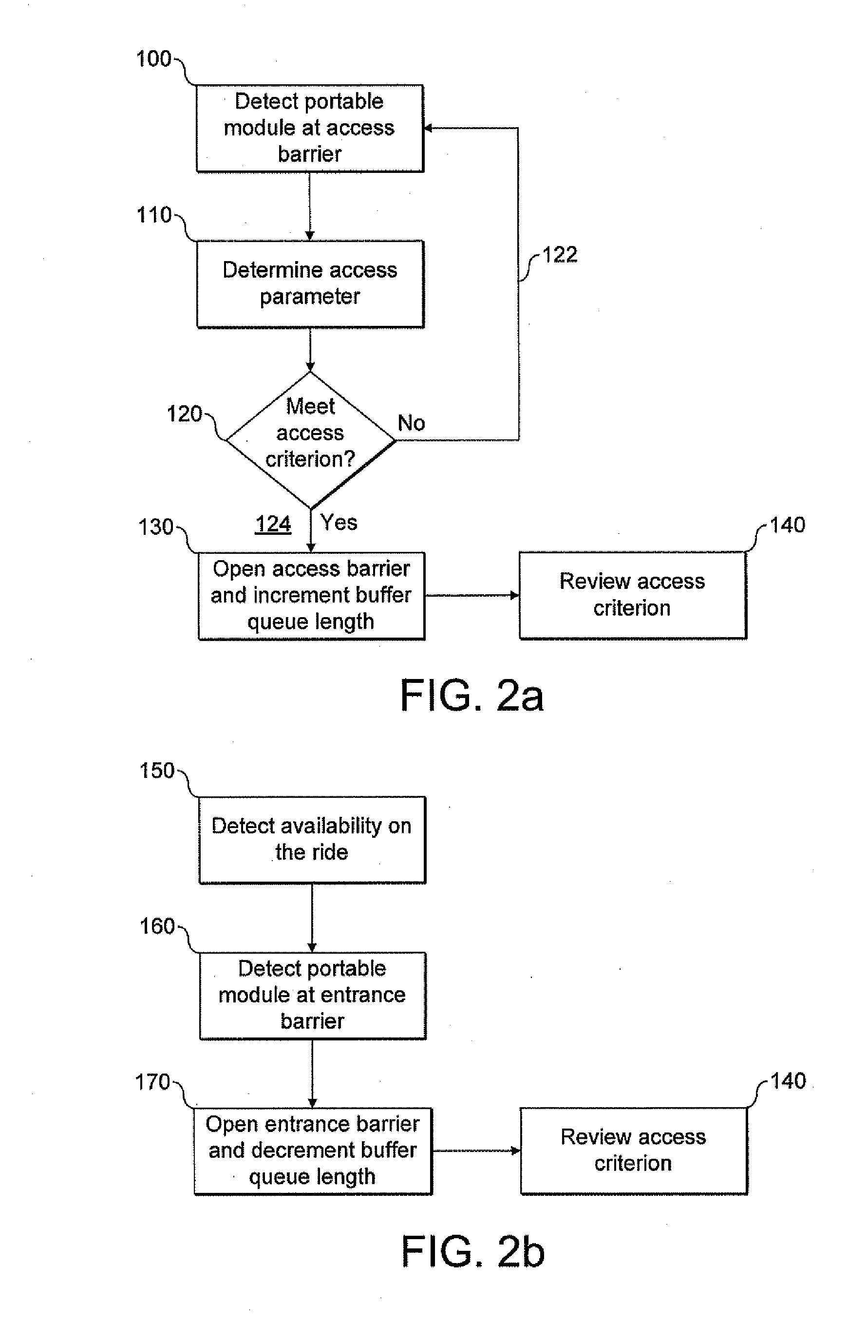
[0055]Referring first to FIG. 1, there is shown a first embodiment of the present invention. Each user is provided with a portable module 10. The user wishes to visit attraction 50. An access barrier 20 and an entrance barrier 30 are provided. The access barrier 20 and the entrance barrier 30 define an access queue 40. The access queue 40 can be further defined by other fences or barriers. Users wishing to use the attraction 50 must pass through access barrier 20 and entrance barrier 30 before reaching the attraction 50. The access barrier 20 has at least two states: a first, open state in which users can pass through the access barrier 20; and a second, closed state, in which the access barrier 20 prevents users from passing though. Similarly, the entrance barrier 30 has at least two states: a first, open state in which users can pass through the entrance barrier 30; and a second, closed state, in which the entrance barrier 30 prevents users from passing though.

[0056]The respective...


PUM


Abstract

A system for regulating access to a resource by a plurality of users is provided. The system comprises: a plurality of portable access keys, each being provided to one of the users and having an associated variable access parameter; an access barrier, having an open state allowing passage through and a closed state denying access to the resource, and defining an access queue; a sensor that determines an access queue characteristic related to a number of users in the access queue; a controller, which sets an access criterion based on the determined access queue characteristic; and a detector, located at the access barrier and which determines the variable access parameter of a portable access key when it is brought into the vicinity of the detector. The controller sets the access barrier in its open state if the variable access parameter determined by the detector meets the access criterion.

Description

TECHNICAL FIELD [0001]This invention relates to a system and method for regulating access to a resource, such as an attraction, ride, show or event, as may be found in an amusement park.BACKGROUND TO THE INVENTION [0002]An amusement park comprises a number of attractions, for example, rides, shows and displays. Each attraction has a limited capacity for people to gain access to it at any specific time. For instance, a ride has only a certain number of seats. It is desirable that access be managed to use the attraction as efficiently as possible and that any regulation of access should be deemed as fair to all users. When more people wish to access the attraction than its instantaneous capacity allows, people who are unable to gain access immediately can be queued.[0003]Physical queue lines are a well known way to manage access. However, the most popular attractions tend to have longer queues for access than less popular attractions. Moreover, potential users of an attraction may bec...

Claims


Application Information

Patent Timeline
IPC IPC(8): G05B19/00
CPCG07C9/00103G07C9/00111G07C2011/04G07C9/02G07C2011/02G07C9/00119G07C9/10G07C9/27G07C9/28G07C9/29
Inventor BAYNE, CHRISTOPHERBUTLER, CHRISTOPHERSIM, LEONARD
Owner LO Q
Learn More