
Safety valve device, valve apparatus, high-pressure gas tank, and vehicle

Active Publication Date: 2010-11-04
TOYOTA JIDOSHA KK +1
View PDF11 Cites 33 Cited by
  • Summary
  • Abstract
  • Description
  • Claims
  • Application Information

AI Technical Summary

Benefits of technology

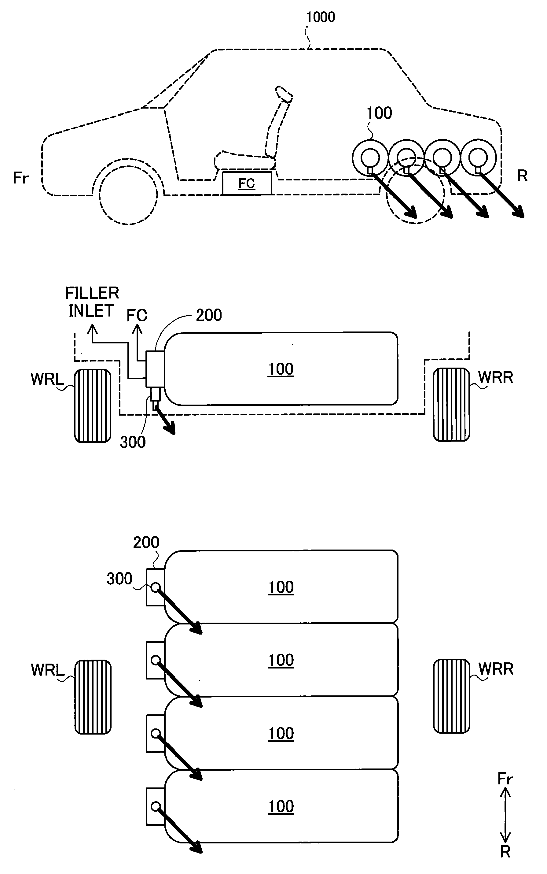
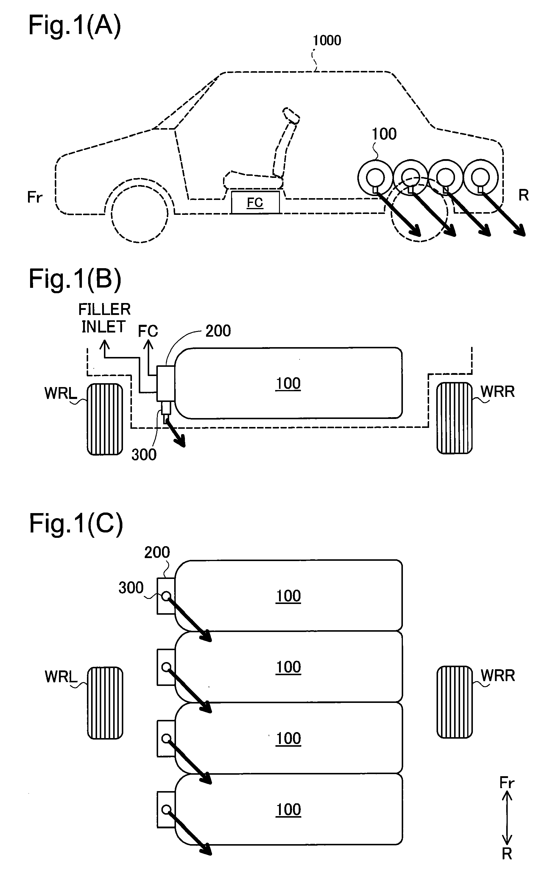
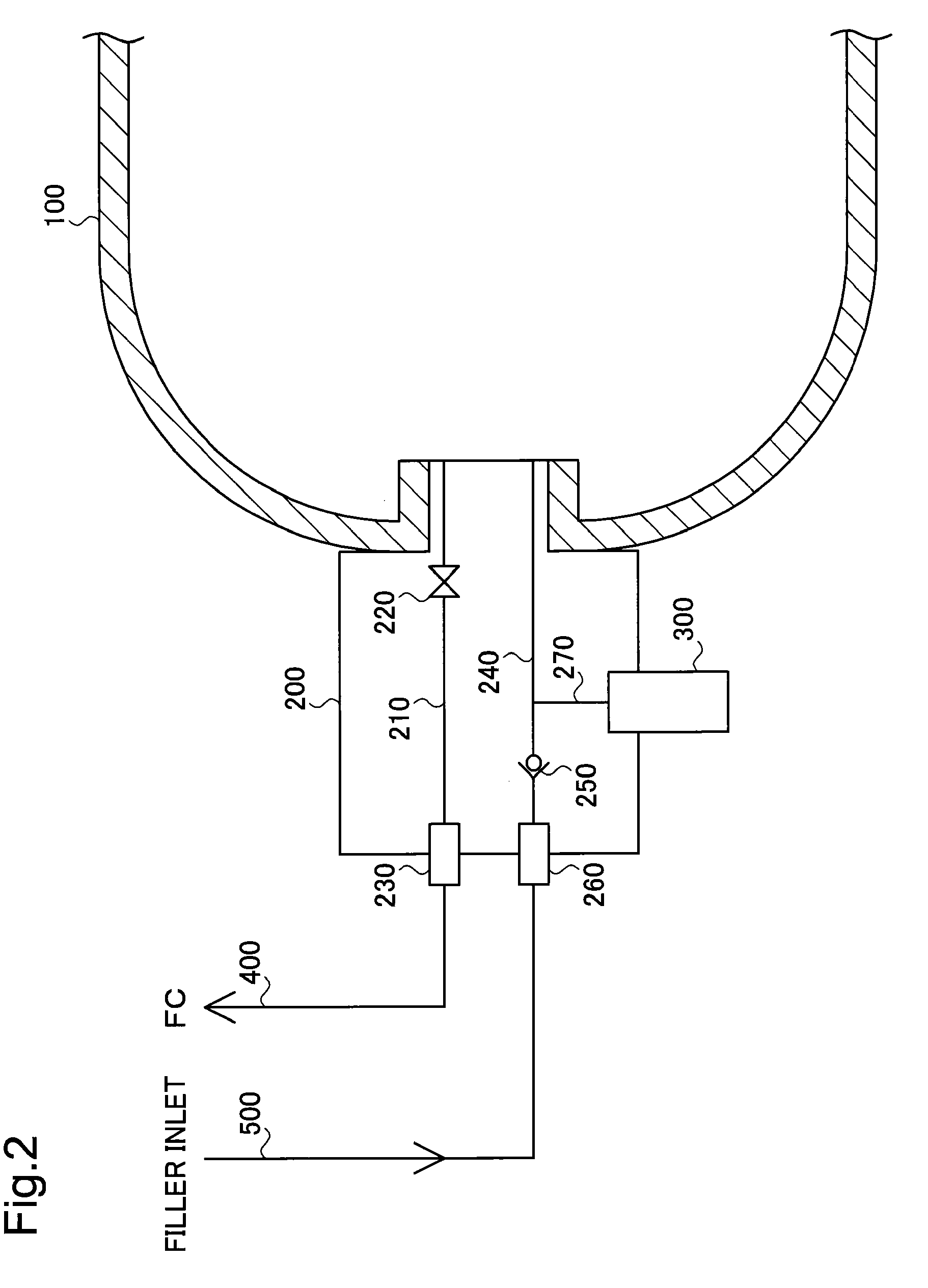
[0009]In the safety valve device according to the above aspect of the invention, the discharge direction of the high-pressure gas from the gas discharge pipe is readily adjustable, in response to application of an externally input rotational force to the gas discharge pipe by the rotation input structure. In the typical application of the high-pressure gas tank with the safety valve device mounted on the vehicle, the safety valve device of the invention can readily adjust the discharge direction of the high-pressure gas. This arrangement effectively improves the performance of adjusting the discharge direction of the high-pressure gas.
[0023]In the vehicle according to this aspect of the invention, the high-pressure tank is installed beneath the floor of the vehicle. In the safety valve device, application of an externally input rotational force to the gas discharge pipe by the rotation input structure enables the discharge direction of the high-pressure gas, which is discharged through the gas discharge opening, to be adjusted to be diagonally backward down from the vehicle and toward the space other than the space for the high-pressure gas tank and the spaces for the wheels of the vehicle. In the structure of the safety valve device, the gas discharge pipe is fastened to the safety valve body. In a normal orientation of the vehicle that is neither rolled nor overturned, when the safety valve device is activated to discharge the high-pressure gas out of the high-pressure gas tank, this arrangement enables the discharged high-pressure gas to be directly hit against the road surface and thereby accelerates the diffusion of the high-pressure gas.

Problems solved by technology

The technique disclosed in Japanese Patent Laid-Open No. 2007-106262, however, may cause the high-pressure gas to be discharged in the forward direction of the vehicle in the active state of the safety valve device.
This may expose the driver and the passengers of the overturned vehicle to danger.
Namely the technique disclosed in Japanese Patent Laid-Open No. 2007-106262 is not capable of adequately adjusting the discharge direction of the high-pressure gas in the active state of the safety valve device.

Method used


Image

  • Safety valve device, valve apparatus, high-pressure gas tank, and vehicle
  • Safety valve device, valve apparatus, high-pressure gas tank, and vehicle
  • Safety valve device, valve apparatus, high-pressure gas tank, and vehicle

Examples


modified example 1

D1. MODIFIED EXAMPLE 1

[0047]The safety valve device 300 of the embodiment discussed above has the groove 336 formed to function as the rotation input structure of the invention. The invention is, however, not restricted to this structure. In general, the rotation input structure may be any element designed to apply a rotational force to the discharge pipe 330 and thereby rotate the discharge pipe 330 around the axial center of the gas flow path 320. By way of example, a projection or a hole formed on the discharge pipe 330 may function as the rotation input structure. In another example, the discharge pipe 330 may be formed in a polygonal columnar shape, which allows a rotational force to be applied to the discharge pipe 330 by means of an adequate tool bit, for example, a screw wrench.

modified example 2

D2. MODIFIED EXAMPLE 2

[0048]In the structure of the embodiment discussed above, the discharge pipe 330 is partly covered with the dust-proof filter 350 made of the waterproof, moisture permeable material. The invention is, however, not restricted to this application. In one modified application, the dust-proof filter 350 may be made of any suitable material having no waterproof property or moisture permeability. In another modified application, the dust-proof filter 350 may be omitted according to the requirements.

[0049]In the structure of the embodiment discussed above, the dust-proof filter 350 is bonded to the discharge pipe 330 by means of the sealing film 360. The invention is, however, not restricted to this arrangement. In one modified arrangement, the dust-proof filter 350 may be bonded to the discharge pipe 330 by means of an adhesive. In another modified arrangement, the dust-proof filter 350 may be fastened to the discharge pipe 330 by means of a cap member or any other s...

modified example 3

D3. MODIFIED EXAMPLE 3

[0050]In the embodiment described above, the binary alloy of bismuth (Bi) and indium (In) is used for both the fusible alloy 312 and the fusible alloy 322. The invention is, however, not restricted to this application. Any other suitable alloy may be used for the fusible alloy 312 and the fusible alloy 322. In one modified application, different alloys may be used for the fusible alloy 312 and the fusible alloy 322. In another modified application, at least one of the fusible alloy 312 and the fusible alloy 322 may be replaced with any other suitable fusible material, such as a resin material.


PUM


Abstract

A safety valve device has a safety valve body configured to include a valve mechanism opened at a temperature of or over a preset reference temperature. The safety valve device also includes a gas flow path arranged to make a flow of hydrogen flowing out of a hydrogen tank via the safety valve body in a valve open position of the valve mechanism, and a discharge pipe configured to have a hydrogen discharge opening and arranged to discharge the hydrogen flowing through the gas flow path to the outside. The hydrogen discharge opening of the discharge pipe is formed to discharge the hydrogen in an oblique direction relative to a direction of an axial center of the gas flow path. The discharge pipe also has a groove formed to apply an input rotational force to the discharge pipe and thereby rotate the discharge pipe around the axial center of the gas flow path. In a typical application of a high-pressure gas tank with such a safety valve device mounted on a vehicle, this arrangement of the safety valve device enables the discharge direction of the high-pressure gas that is discharged from the safety valve device to be readily adjusted.

Description

TECHNICAL FIELD[0001]The present invention relates to a safety valve device used for a high-pressure gas tank configured to store a high-pressure gas, as well as to a valve apparatus, the high-pressure gas tank, and a vehicle equipped with the high-pressure gas tank.BACKGROUND ART[0002]Diversity of vehicles, such as fuel cell vehicles and hydrogen vehicles, have been developed to be equipped with a high-pressure gas tank for storing a high-pressure gas, such as compressed hydrogen, and to be driven with the high-pressure gas stored in the high-pressure gas tank as a fuel gas.[0003]A valve apparatus is generally connected to the high-pressure gas tank for storing the high-pressure gas (compressed gas or liquefied gas) to discharge the high-pressure gas from inside to outside of the high-pressure gas tank and to fill the high-pressure gas from outside to inside of the high-pressure gas tank. A safety valve device is typically connected with the valve apparatus to discharge the high-pr...

Claims


Application Information

Patent Timeline
IPC IPC(8): F16K17/00
CPCB60K15/07Y02E60/50B60K2001/0433B60K2015/0638F17C2201/0109F17C2201/0119F17C2201/035F17C2201/056F17C2205/013F17C2205/0317F17C2205/0326F17C2205/0332F17C2205/0335F17C2205/0341F17C2205/0385F17C2205/0394F17C2221/012F17C2223/0123F17C2223/035F17C2260/021F17C2270/0178F17C2270/0184H01M8/04089H01M8/04201H01M16/006H01M2250/20Y02E60/321Y02T90/32B60K2001/0416B60K2015/03026B60K2015/03315B60K2015/03375Y02E60/10Y02E60/32Y02T90/40Y10T137/1797Y10T137/1963Y10T137/6855Y10T137/6892Y10T137/7737
Inventor IIDA, YASUYUKIYAMAMOTO, YASUHIROTANO, YUTAKADAIDO, KUNIHIKO
Owner TOYOTA JIDOSHA KK
Learn More