
Whole smoke exposure apparatus

a whole smoke and apparatus technology, applied in tobacco, biomass after-treatment, instruments, etc., can solve the problems of reducing the exposure efficiency of cells to a particulate phase portion in the sample, affecting the efficiency of smoking exposure, and affecting the effect of smoking exposur

Inactive Publication Date: 2010-10-28
FUKANO YASUO +2
View PDF3 Cites 15 Cited by
  • Summary
  • Abstract
  • Description
  • Claims
  • Application Information

AI Technical Summary

Benefits of technology

[0013]It is an object of the present invention to provide a whole smoke exposure apparatus which allows cells to be sufficiently and efficiently exposed to smoke even in an exposure test using smoke containing a particulate phase and / or a vapor phase as a sample.

Problems solved by technology

According to the exposure principle of bringing the sample into contact with the cell surface through the continuous flow of air in exposing a cell surface to a sample, the cell surface may not be sufficiently exposed to smoke containing a particulate phase.
However, a sample in a particulate phase is exhausted through the flow of air continuously flowing in a non-sealed chamber because of the size of particles.
This causes a considerable reduction in exposure efficiency of exposure of cells to a particulate phase portion in the sample.

Method used


Image

  • Whole smoke exposure apparatus
  • Whole smoke exposure apparatus
  • Whole smoke exposure apparatus

Examples


first embodiment

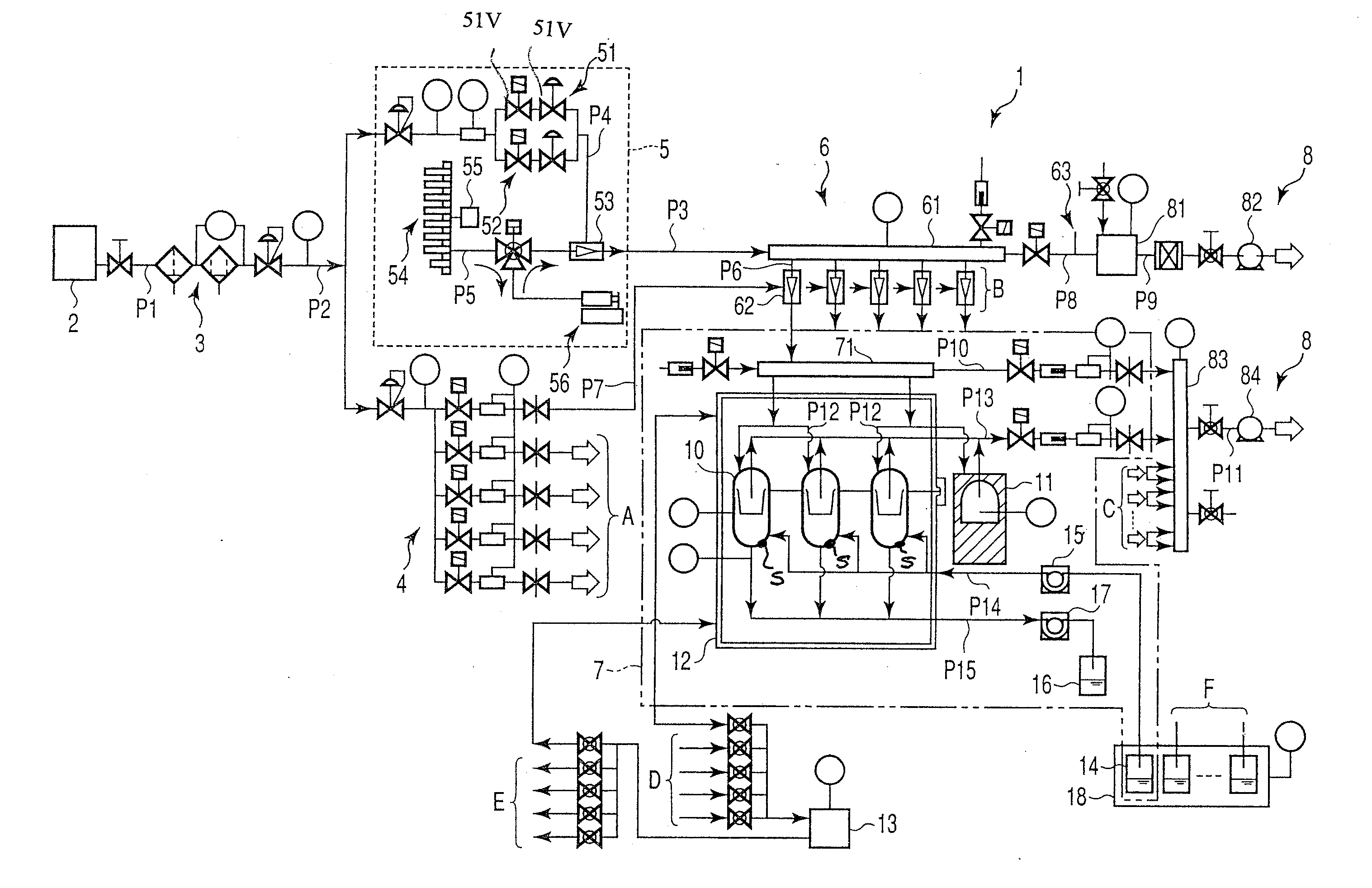
[0046]a whole smoke exposure apparatus according to the present invention will be described in detail below with reference to FIGS. 1 to 3. Referring to FIG. 1, the whole smoke exposure apparatus denoted by reference numeral 1 has a compressor 2. The compressor 2 supplies compressed air to a clean air unit 3 connected thereto through a pipe line P1. The clean air unit 3 is connected to a clean air supply section 4 and smoke emitting section 5 through a pipe line P2 branched into two lines. The smoke emitting section 5 is connected to a dilution means 6 through a pipe line P3. The dilution means 6 is connected to the clean air supply section 4 through a pipe line P7.

[0047]The smoke emitting section 5 has a diluent air section 51, clean air section 52, and concentration setting section 53. The diluent air section 51 having a pair of valves 51V and clean air section 52 are connected to the two pipe lines branching from the pipe line P2. The pipe lines P2 become a single pipe line P4 ag...

second embodiment

[0092]In the second embodiment, the smoke emitted by the smoke emitting section 5 can flow into a plurality of chambers 10, as samples uniform in concentration and amount, from the manifold 65 connected to the header 64 through the concentration setting section 63. This allows a high-precision exposure test in a whole smoke exposure apparatus 1 having a plurality of chambers 10, and increases the exposure efficiency. In addition, the installation of the manifold 65 between the header 64 and the concentration setting section 63 makes it possible to stabilize the behavior of diluted smoke and introduce homogenous smoke into the chambers 10.

[0093]A culture medium is supplied into the chamber 10 through an inlet positioned at the bottom portion of the chamber, and is discharged through an outlet positioned above the inlet. This can prevent the occurrence of air bubbles in a culture medium.

[0094]Other operations and effects in the second embodiment are the same as those in the first embo...


PUM


Abstract

An apparatus includes a smoke emitting section which emits smoke containing particulate matter, a dilution section for diluting the smoke emitted by the smoke emitting section, a clean air unit which supplies clean air to the dilution section, at least one chamber which incorporates a cell-adhered surface and into which the smoke diluted by the dilution section is introduced, and an exhaust section for exhausting the smoke from the chamber and the dilution section. A smoke flow in the chamber is shut off to make the smoke settle down in the chamber and expose the cell-adhered surface to the smoke.

Description

CROSS-REFERENCE TO RELATED APPLICATIONS[0001]This is a Continuation Application of U.S. patent application Ser. No. 10 / 793,774, field Mar. 8, 2004, and PCT Application No. PCT / JP02 / 03399, filed Apr. 4, 2002, which was not published under PCT Article 21(2) in English.[0002]This application is based upon and claims the benefit of priority from prior Japanese Patent Application No. 2001-303668, filed Sep. 28, 2001, the entire contents of which are incorporated herein by reference.BACKGROUND OF THE INVENTION[0003]1. Field of the Invention[0004]The present invention relates to an apparatus for exposing cells to smoke containing particulate matter. This apparatus is aimed for exposure tests of cells to aerosols such as tobacco smoke. However, the apparatus is not limited to them and may be applied to exposure tests using other samples.[0005]2. Description of the Related Art[0006]As apparatuses for exposing cultured cells to samples such as smoke and checking their influences on the cells,...

Claims


Application Information

Patent Timeline
IPC IPC(8): C12M1/00A24C5/34C12M3/00G01N17/00
CPCA24C5/3406C12M41/34C12M35/08
Inventor FUKANO, YASUOSUZUKI, MUTSUAKIIDE, MAIKO
Owner FUKANO YASUO
Learn More