
Radial flow oxygenator/heat exchanger

a technology of oxygenator and heat exchanger, which is applied in the direction of blood pump, circulatory assistance device, other medical devices, etc., can solve the problems of low pressure drop within the apparatus, reduce the chance of blood clots, reduce the chance of recirculation of blood or stagnant areas, and save patient us

Inactive Publication Date: 2010-10-28
MEDTRONIC INC
View PDF2 Cites 26 Cited by
  • Summary
  • Abstract
  • Description
  • Claims
  • Application Information

AI Technical Summary

Benefits of technology

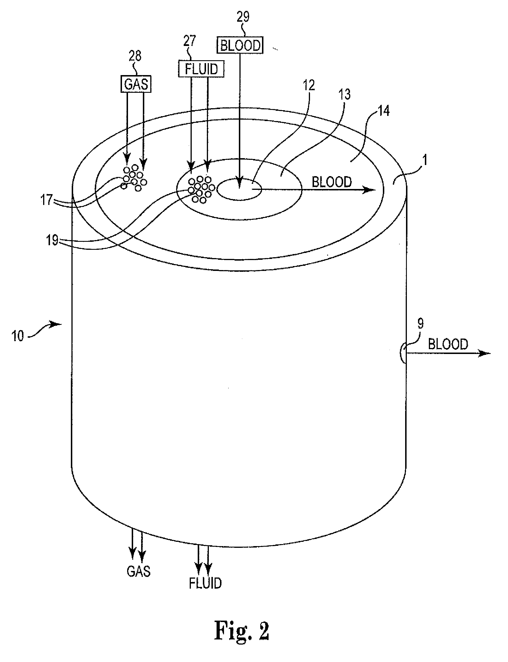
The present invention provides an apparatus for oxygenating and controlling the temperature of blood in a cardiopulmonary bypass circuit. The apparatus includes a heat exchanger and an oxygenator, which are designed to allow blood to flow radially and sequentially through the heat exchanger and oxygenator. This design increases the overall performance and efficiency of the apparatus and ensures optimal distribution of blood over surface area used for gas and heat exchange. The apparatus is safer for patients, reduces recirculation of blood, and minimizes shear forces that can traumatize blood cells. The design also eliminates certain components necessary in prior art devices, reduces the prime volume of blood necessary for the patient, and improves manufacturability over other similar devices. The apparatus is housed in a housing with a blood inlet, blood outlet, fluid medium inlet, and fluid medium outlet. The plurality of heat transfer elements and gas exchange elements may be arranged concentrically about the inlet mandrel or wound on the inlet mandrel and heat exchanger. The apparatus is efficient, safe, and easy to manufacture.

Problems solved by technology

The radial flow also results in a low pressure drop within the apparatus.

Method used


Image

  • Radial flow oxygenator/heat exchanger
  • Radial flow oxygenator/heat exchanger
  • Radial flow oxygenator/heat exchanger

Examples


Embodiment Construction

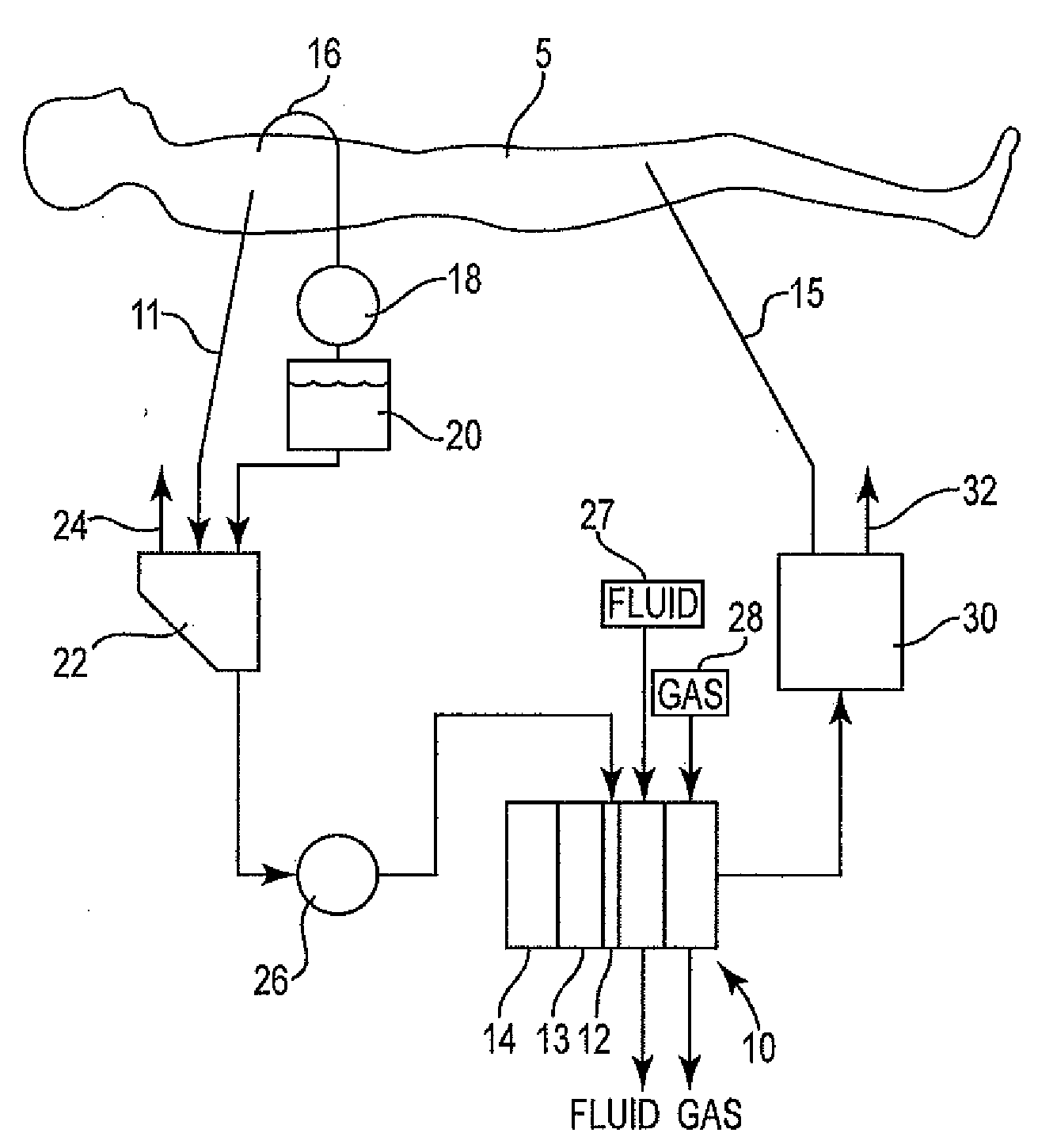
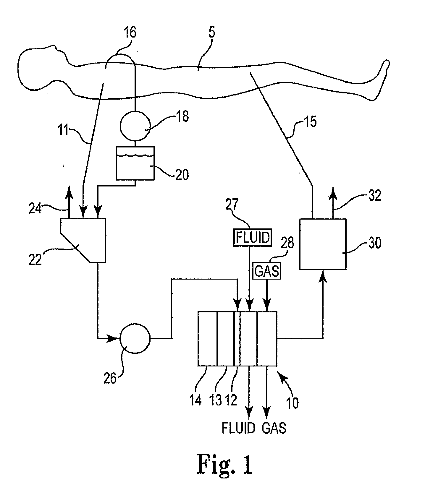
[0045]Referring to FIG. 1, an exemplary cardiopulmonary bypass circuit is schematically illustrated, which includes an embodiment of an apparatus 10 in accordance with the invention. The circuit generally draws blood of a patient 5 during cardiovascular surgery through a venous line 11, oxygenates the blood, and returns the oxygenated blood to the patient 5 through an arterial line 15. Venous blood drawn from the patient through line 11 is discharged into a venous reservoir 22. Cardiotomy blood and surgical field debris are aspirated by a suction device 16 and are pumped by pump 18 into a cardiotomy reservoir 20. Once defoamed and filtered, the cardiotomy blood is also discharged into venous reservoir 22. Alternatively, the function of the cardiotomy reservoir 20 may be integrated into the venous reservoir 22. In the venous reservoir 22, air entrapped in the venous blood rises to the surface of the blood and is vented to the atmosphere through a purge line 24.

[0046]A pump 26 draws b...


PUM


Abstract

Described is an apparatus for oxygenating and controlling the temperature of blood in an extracorporeal circuit comprising: an inlet mandrel that is configured such that the blood moves radially outward from the inlet mandrel through the openings in a radial direction; a heat exchanger arranged around the inlet mandrel, wherein blood can move radially outward with the transfer of heat to or from the blood; an oxygenator arranged around the heat exchanger, wherein blood can move from the heat exchanger radially outward with the transfer of oxygen into the blood; and a housing that houses the inlet mandrel, the heat exchanger and the oxygenator, and that comprises a blood inlet in communication with the inlet mandrel in order to allow blood to enter the apparatus from the patient, and a blood outlet in communication with the oxygenator in order for blood to exit the apparatus, wherein the blood outlet is located in the housing radially outward from the inlet.

Description

FIELD OF THE INVENTION[0001]The invention generally relates to cardiopulmonary bypass circuits, and particularly to an apparatus that includes a heat exchanger, an oxygenator, a core, and an optional pump that may be arranged around each other. For example, one embodiment of the apparatus includes a core, a heat exchanger arranged about the core, an oxygenator arranged about the heat exchanger, to which blood is delivered into the core, that optionally comprises a pump, and through which blood moves radially outward from the apparatus, with a fluid medium being supplied separately to the heat exchanger and a gas medium being supplied separately to the oxygenator in directions generally transverse to the radial movement of the blood.BACKGROUND OF THE INVENTION[0002]A cardiopulmonary bypass circuit (i.e., a heart-lung bypass machine) mechanically pumps a patient's blood and oxygenates the blood during major surgery. Blood oxygenators are disposable components of heart-lung bypass mach...

Claims


Application Information

Patent Timeline
Patent Type & Authority Applications(United States)
IPC IPC(8): A61M1/36A61M60/113A61M60/232A61M60/279A61M60/38A61M60/508
CPCA61M1/1698A61M1/1006A61M2206/16A61M60/113A61M60/38A61M60/232A61M60/279A61M60/508A61M1/3623
Inventor CARPENTER, WALT L.OLSEN, ROBERT W.HOBDAY, MICHAEL J.MCLEVISH, ALFORD L.PLOTT, CHRISTOPHER J.BRISCOE, RODERICK E.CLOUTIER, PARTICK J.THAPA, ANILLI, MINGMCINOTOSH, KEVIN
Owner MEDTRONIC INC
Learn More