
Method and device for conveying particulate material during the layer-wise production of patterns

a technology of layer-wise production and conveying device, which is applied in the direction of transportation and packaging, additive manufacturing processes, manufacturing tools, etc., can solve the problems of uneven filling across the length of the spreader device, one fill level control is always necessary, and can only be compensated to an unsatisfactory degr

Active Publication Date: 2010-10-28
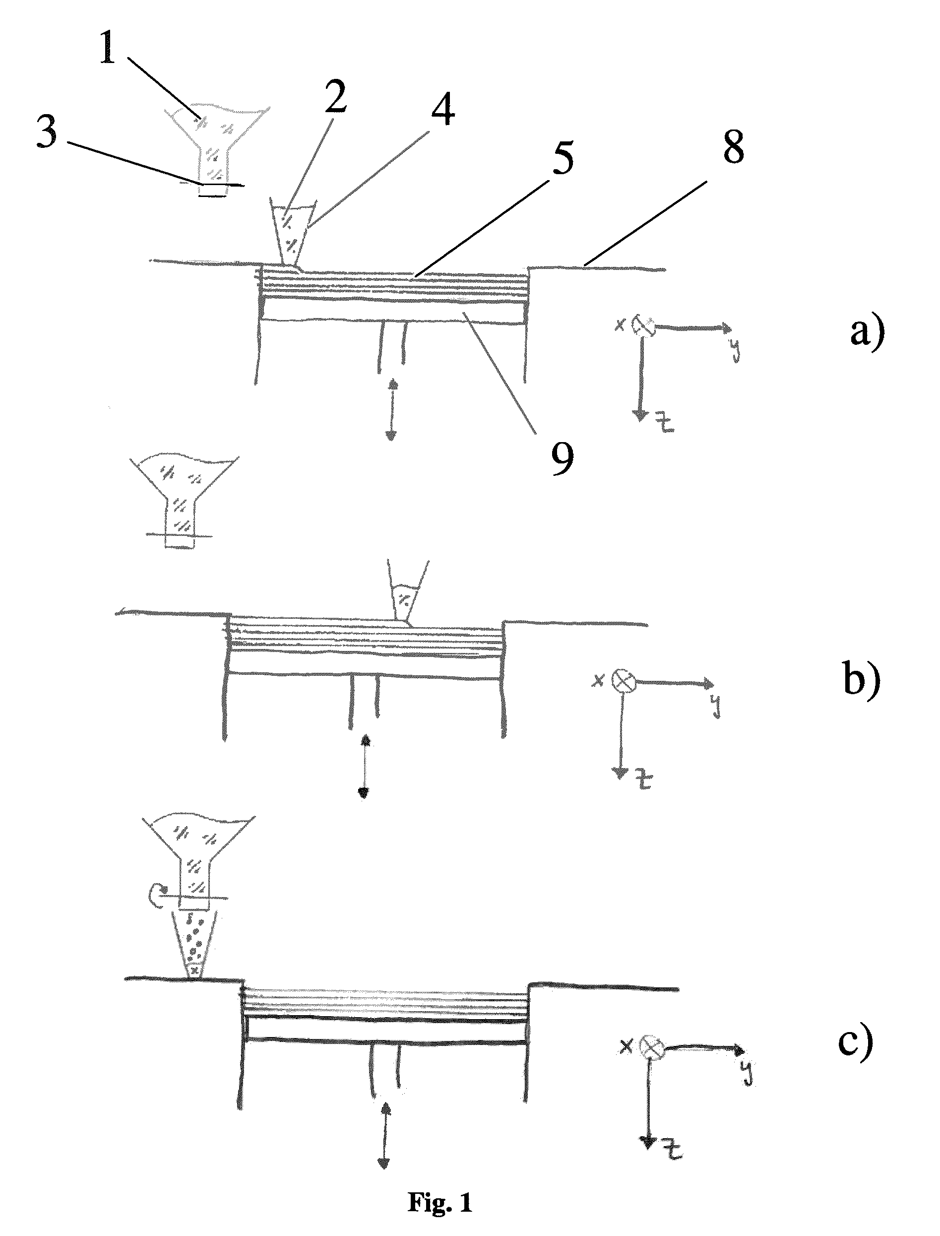
VOXELJET AG
View PDF112 Cites 73 Cited by
  • Summary
  • Abstract
  • Description
  • Claims
  • Application Information

AI Technical Summary

Benefits of technology

[0017]It is thus the objective of the present invention to provide a method and a device to refrain from using a fill level control and to evenly fill the spreader device across the entire length.

Problems solved by technology

In the case of these methods and devices for filling a spreader unit for fluids, which are known from the state of the art, it has proven to be disadvantageous that one fill level control is always necessary.
An uneven filling across the length of the spreader device can furthermore only be compensated for to an unsatisfactory degree with the methods from the state of the art.

Method used


Image

  • Method and device for conveying particulate material during the layer-wise production of patterns
  • Method and device for conveying particulate material during the layer-wise production of patterns
  • Method and device for conveying particulate material during the layer-wise production of patterns

Examples


Embodiment Construction

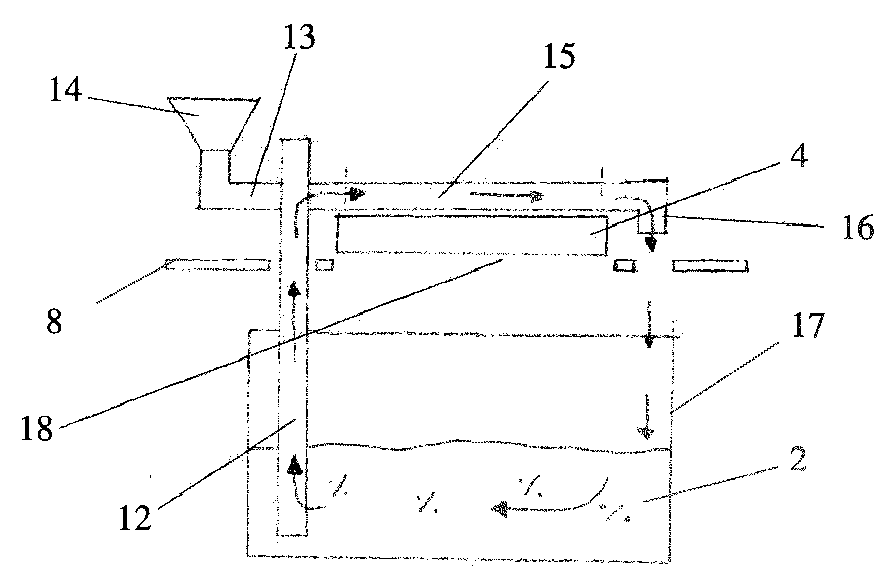
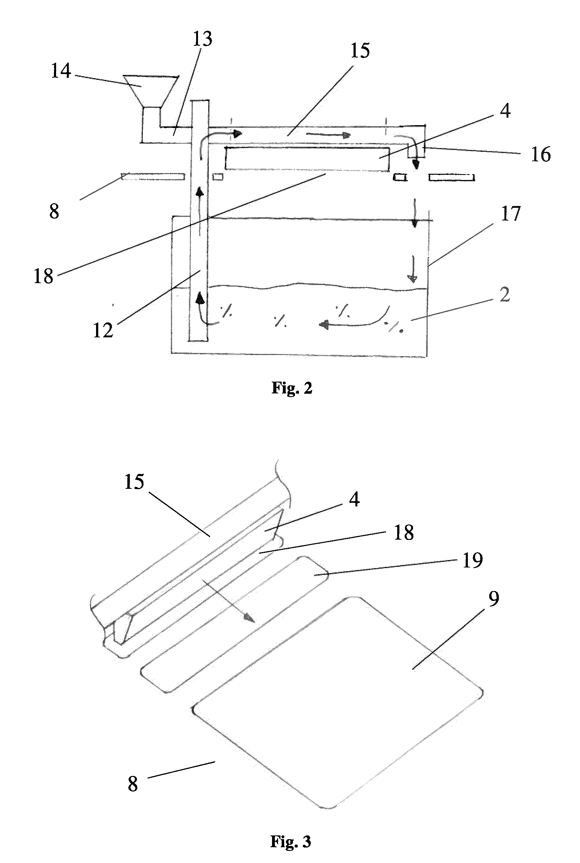
[0036]According to the present invention, a closed conveying system thus refers to a system, in the case of which a conveying to the spreader device system takes place and from there also back into the reservoir, if applicable.

[0037]According to a preferred embodiment of the present invention, the conveying of powder could take place via screw conveyors.

[0038]Apart from this or in addition thereto, it would also be possible for the conveying of powder to take place via low pressure.

[0039]A conveying via low pressure can be advantageous in particular when the conveying is to take place in a conveying system, which is closed off from the environment.

[0040]In the case of the method according to the invention, it can furthermore be advantageous when the conveying of powder of the conveying circuit takes place via an individual conveying system. The different conveying systems must then possibly not be coordinated.

[0041]However, it is also possible for the conveying of powder of the conv...


PUM

PropertyMeasurementUnit
Pressureaaaaaaaaaa
Angleaaaaaaaaaa

Abstract

The present invention relates to a method for conveying particulate material during the manufacture of patterns in layers, wherein powder is conveyed out of a reservoir into a spreader unit and, if applicable, excess powder fed to the spreader unit is again conveyed back into the reservoir and wherein this conveying takes place in a closed conveying circuit.

Description

CLAIM OF PRIORITY[0001]This application is a national phase of PCT application No. PCT / DE2008 / 001602, filed Oct. 6, 2008, which claims priority to German Application No. DE 10 2007 050 679.3, filed Oct. 21, 2007, all of which are incorporated by reference herein.FIELD OF THE INVENTION[0002]The invention relates to a method and to a device for conveying particulate material during the manufacture of patterns in layers.BACKGROUND[0003]Methods for producing three-dimensional components have already been known for a long time.[0004]European patent specification EP 0 431 924 B1, for example, describes a method for producing three-dimensional objects from computer data. A particulate material is thereby applied onto a platform in a thin layer and said platform is selectively imprinted with a binder material by means of a print head. The particulate area, which is imprinted with the binder, adheres and solidifies under the impact of the binder and an additional hardener, if applicable. The...

Claims


Application Information

Patent Timeline
IPC IPC(8): B65G53/40B65G47/00B65G33/08
CPCB05C19/06B22F3/008B22F2998/00B29C67/0081B29C67/0077B22F3/003B29C64/141B29C64/153B29C64/165B33Y10/00B33Y30/00B33Y40/00B29C64/35B29C64/357B22F10/10Y02P10/25B22F12/60B22F10/73B22F2998/10B29K2105/251
Inventor EDERER, INGOHARTMAN, ANDREAS
Owner VOXELJET AG
Learn More