
Charged particle beam therapy system having an x-ray imaging device

Inactive Publication Date: 2010-10-28
ION BEAM APPL
View PDF5 Cites 106 Cited by
  • Summary
  • Abstract
  • Description
  • Claims
  • Application Information

AI Technical Summary

Benefits of technology

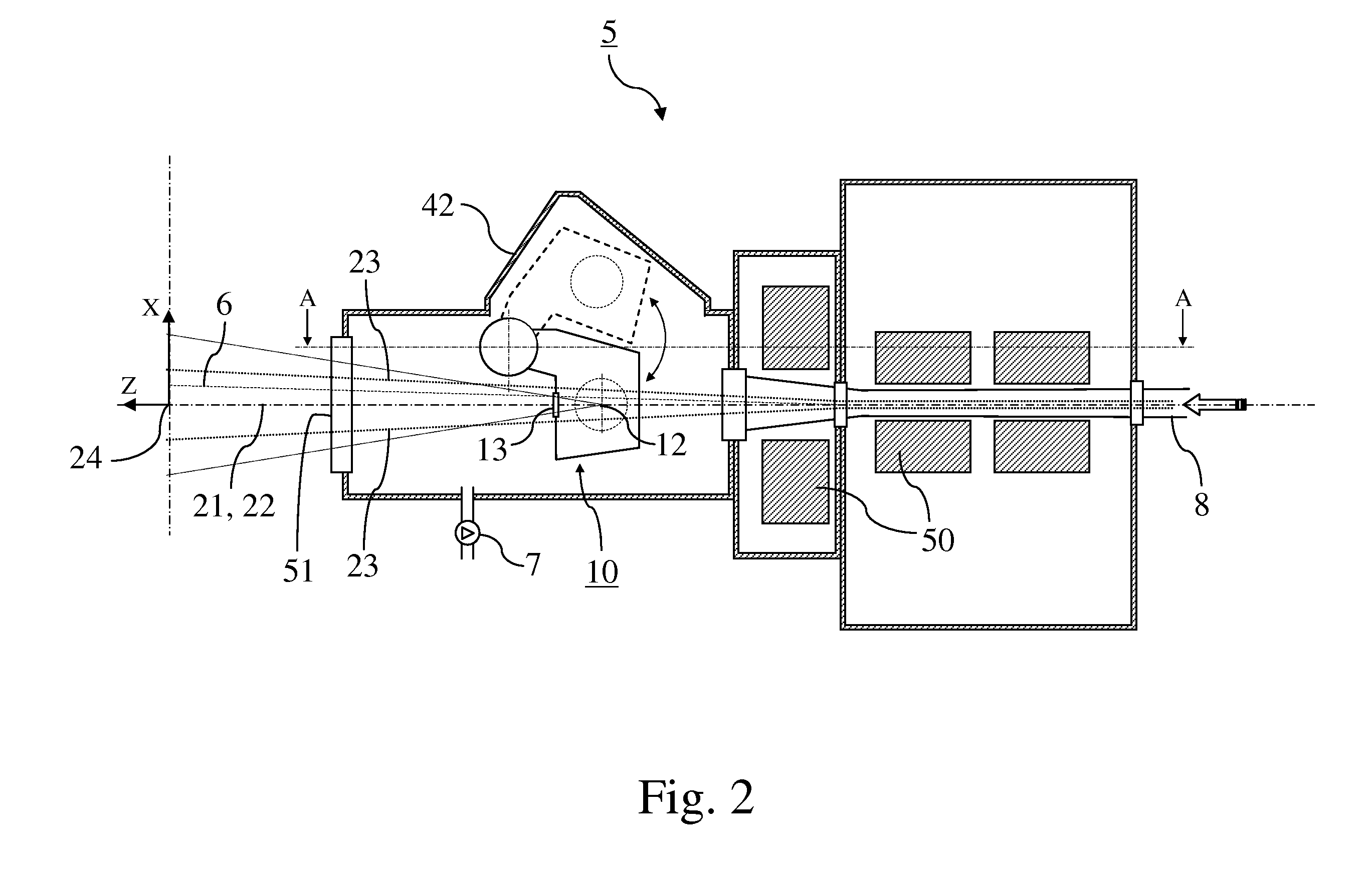
[0017]With a system according to the invention, the number and the complexity of the mechanical parts required for moving the X-Ray device between its two positions is reduced, which is particularly attractive in a vacuum environment. The bulk of the system is also reduced since only a rotation axle is to be permanently outside of the treatment path envelope of the beam, whereas, as can be seen for example from FIG. 3 of patent publication number WO 98 / 18523, the complete mechanical device for moving the X-Ray device, including a.o. the two guiding tracks, must be permanently outside of said envelope in the known systems. Furthermore, with a system according to the invention, the displacement of electrical and fluid ducts to the X-Ray device can also be made smaller, thereby putting less strain on said ducts and increasing their durability.
[0020]With such a preferred therapy system, air at the external air pressure can enter into the container through the open side of its neck and hence all parts which are arranged inside of the container, such as the X-Ray source for example, will be at the external air pressure, yet maintaining the vacuum inside the nozzle even when the X-Ray device is rotating about its rotation axis. An additional advantage of such a preferred therapy system is that electrical and fluid ducts can easily be passed from the outside of the nozzle, through the open side of the neck, to the X-Ray source, along a path which is thus completely at the external air pressure. Furthermore, since the axis of the cylindrical neck is the rotation axis, said ducts can for example be arranged along the rotation axis, which further reduces strain on said ducts when the X-Ray device moves between its two positions.
[0023]In addition to the fact that the driving means will thereby be subject to the external air pressure, such a preferred therapy system presents the further advantage that the driving means will be easily accessible for inspection and / or maintenance.

Problems solved by technology

Although such known systems work well, they require a relatively complex and hence expensive mechanical assembly for moving the X-Ray device.
Now, many of the standard mechanical components which are being used for moving the X-Ray device in the known systems are not suited for operating in a vacuum and would therefore have to be redesigned and / or reengineered for operation in such an environment.
This would in turn increase the complexity, the costs, and most probably the weight and the bulk of the system.

Method used


Image

  • Charged particle beam therapy system having an x-ray imaging device
  • Charged particle beam therapy system having an x-ray imaging device
  • Charged particle beam therapy system having an x-ray imaging device

Examples


Embodiment Construction

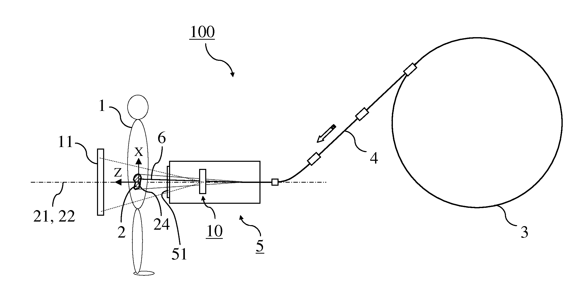
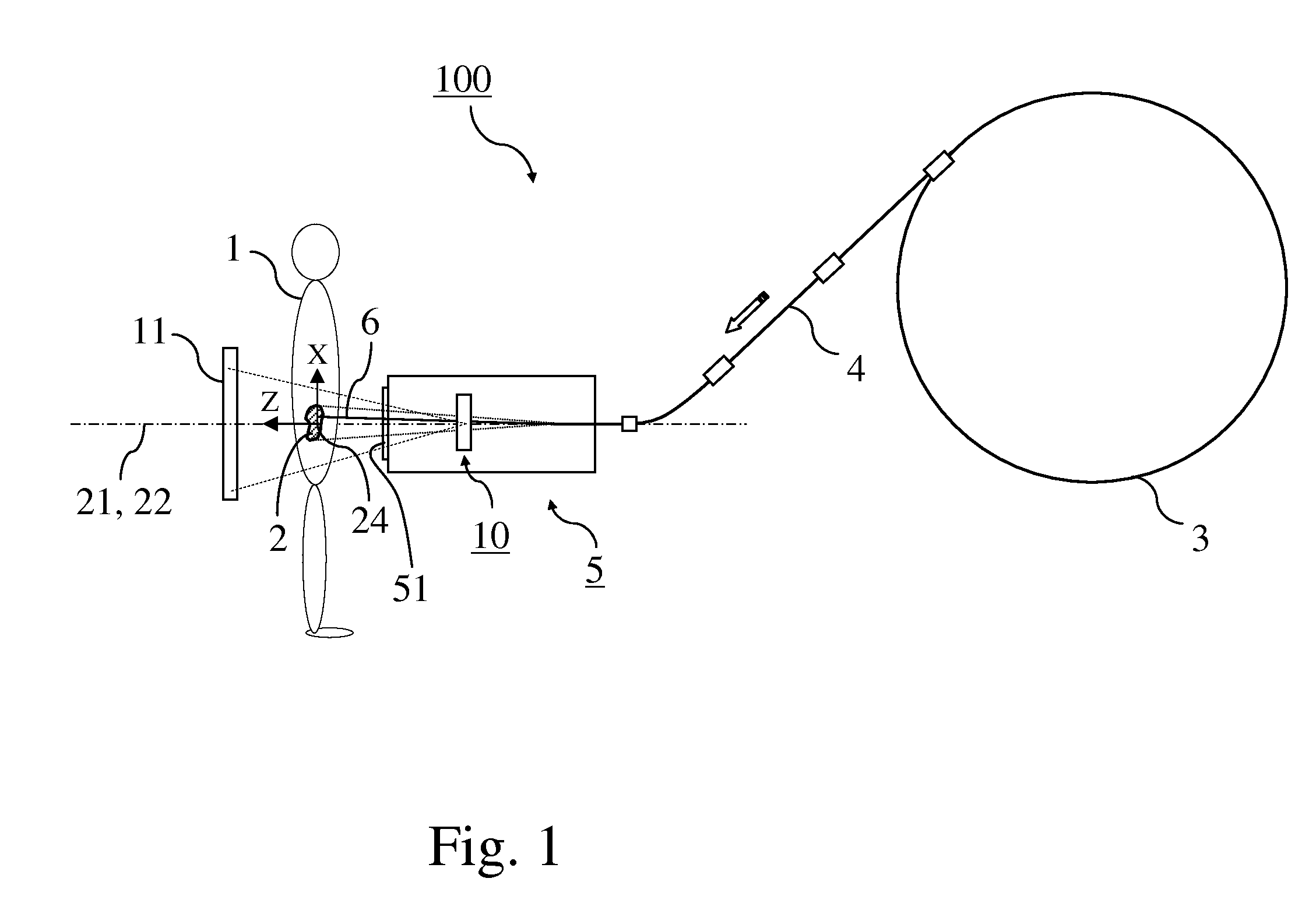
[0031]FIG. 1 shows a schematic view of a charged particle beam therapy system 100 according to the invention.

[0032]Such therapy system 100 comprises a charged particle beam generator 3 for generating a beam of charged particles, such as protons or carbon ion particles or any other type of charged particle, a beam transport system 4 for transporting the charged particle beam 6 from the generator 3 along a beam path, and a nozzle 5 at an end of such path for delivering the charged particle beam 6 to a target volume 2 within a patient 1. Such a nozzle 5 may apply various target irradiation methods such as beam scattering, beam wobbling, pencil beam scanning, and other methods. The nozzle 5 may be mounted on a gantry for rotation of the nozzle 5 about an isocenter 24 of the system or may be of the fixed beam line type or of any other type.

[0033]The nozzle 5 comprises an X-Ray device 10 which includes an X-Ray source 12 for emitting X-Rays towards the target volume 2 so as to substantial...


PUM


Abstract

Therapy system (100) for irradiating a target volume (2) of a patient (1) with a charged particle beam (6), including a beam generator (3), a beam transport system (4), and a nozzle (5) for distributing the beam to the target volume (2), the nozzle (5) being, when in operation, under vacuum. The therapy system comprises an X-ray device (10) which is rotatably mounted inside the nozzle (5) between a first position and a second position. In the first position, an X-Ray source (12) within the X-Ray device is able to emit X-Rays along a charged particle beam path for generating an X-Ray image on a corresponding X-Ray receiving device (11) arranged opposite to the patient (1), said X-Ray image serving to determine a correct position of the target volume (2) with regard to the charged particle beam (6). In the second position, the X-Ray device (10) is set outside of a charged particle beam treatment path envelope (23), so that the charged particle beam (6) can reach and irradiate the target volume (2).

Description

BACKGROUND OF THE INVENTION[0001](1) Field of the Invention[0002]The invention relates to a therapy system for irradiating a target volume within a patient with a charged particle beam, comprising[0003]a charged particle beam generator,[0004]a beam transport system for transporting the charged particle beam,[0005]a nozzle for delivering the charged particle beam to the target volume,[0006]an X-Ray device comprising an X-Ray source for emitting X-Rays towards the target volume, the X-Ray device being movably mounted into the nozzle between a first position wherein the X-Ray device is inside of a treatment path envelope of the charged particle beam within the nozzle and a second position wherein the X-Ray device is outside of said treatment path envelope,[0007]an X-Ray receiving device mounted opposite to the patient with regard to the X-Ray source, and in optical alignment with the X-Ray source when the X-Ray device is in the first position,[0008](2) Description of Related Art[0009]S...

Claims


Application Information

Patent Timeline
IPC IPC(8): H05G1/02
CPCA61N5/1049A61N2005/1087A61N2005/1061
Inventor AMELIA, JEAN-CLAUDEGENIN, FREDERIC
Owner ION BEAM APPL
Learn More