
Start test electronic device and system and method of use thereof

a technology for starting motors and electronic devices, which is applied in the field of system for monitoring and testing the safe operation of power generators, and can solve problems such as the inability to provide notice of parallel installation of starter motors, the inability to predict the failure of the starter motor at an accelerated pace, and the entire amperage load

Active Publication Date: 2010-10-28
DARBY GROUP
View PDF10 Cites 19 Cited by
  • Summary
  • Abstract
  • Description
  • Claims
  • Application Information

AI Technical Summary

Benefits of technology

[0014]Another aspect of the present invention is to provide a method and system that will give a warning to a system operator of a failure of either starter motor in a power generating system and the ability to effectively predict the same.

Problems solved by technology

Failure of the starter motors has a cascading affect on the system, thus causing failure.
Unfortunately, in current systems, the parallel installation of the starter motors does not provide notice if the first starter motor fails to operate.
If the first motor does fail to operate, then the second starter motor will bear the strain of a dual load, leading to its unpredictable and eventual failure at an accelerated pace.
If the first motor fails, then the second motor draws the entire amperage load.
Currently available monitoring systems do not exist, or are not adequate in their profile building, so there is little or no means of predicting failure in the second starter motor.
As a result of system failure involving second starter motors, it is often determined in post-operative analysis that both motors had failed: the first through various defects or anomalies; and, the second through overload of the starter relays, or through failure of a starter solenoid, winding failures, bearing failures or several other failure modes.
Many of these failure modes are accelerated by severe stress from having to bear the full amperage load together with a failure in preventative or predictive maintenance.

Method used


Image

  • Start test electronic device and system and method of use thereof
  • Start test electronic device and system and method of use thereof
  • Start test electronic device and system and method of use thereof

Examples


Embodiment Construction

[0031]Reference will now be made in detail to several embodiments of the invention that are illustrated in the accompanying drawings. Wherever possible, same or similar reference numerals are used in the drawings and the description to refer to the same or like parts or steps. The drawings are in simplified form and are not to precise scale. For purposes of convenience and clarity only, directional terms, such as top, bottom, up, down, over, above, and below may be used with respect to the drawings. These and similar directional terms should not be construed to limit the scope of the invention in any manner. The words “connect,”“couple,” and similar terms with their inflectional morphemes do not necessarily denote direct and immediate connections, but also include connections through mediate elements or devices.

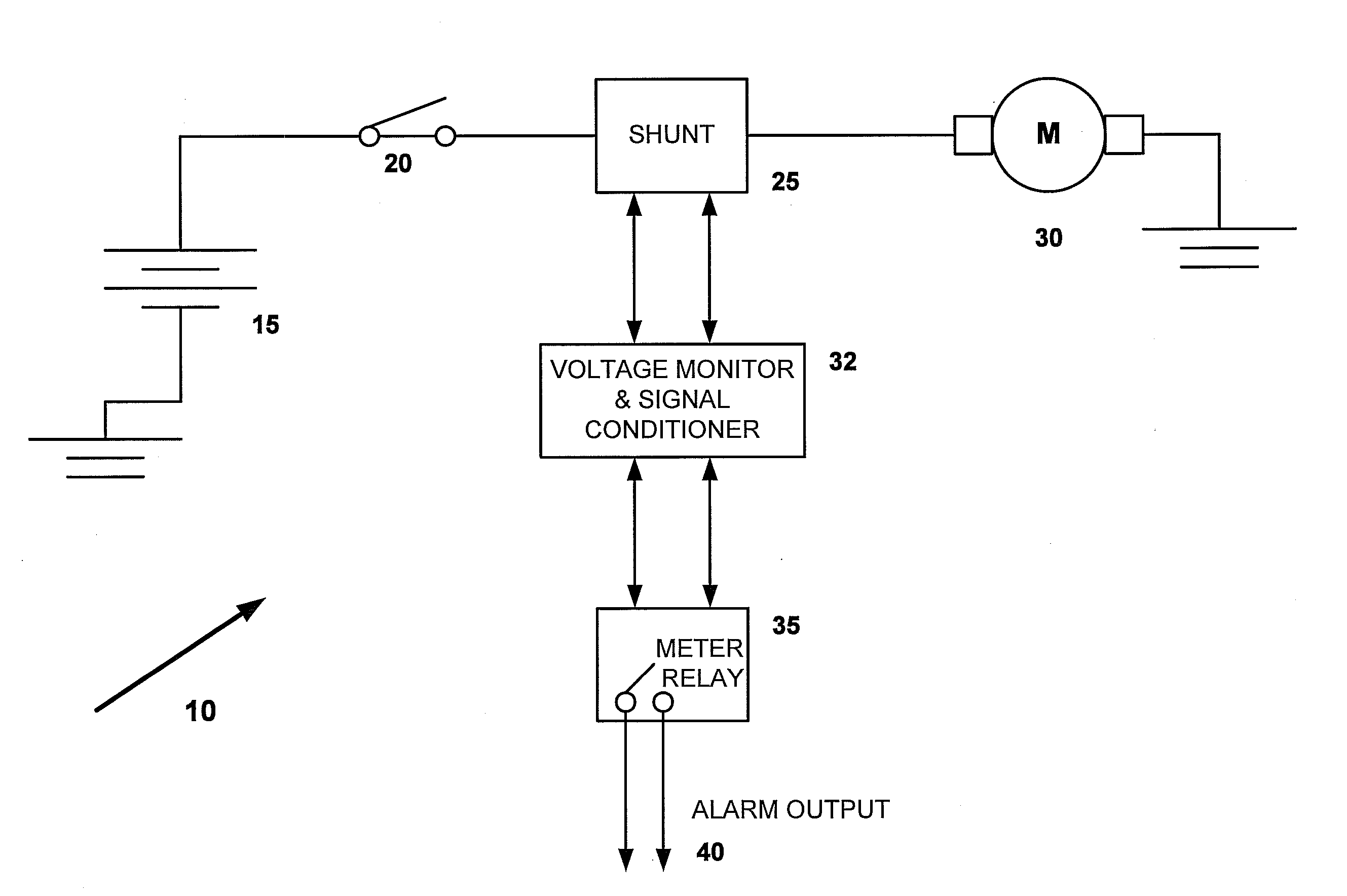
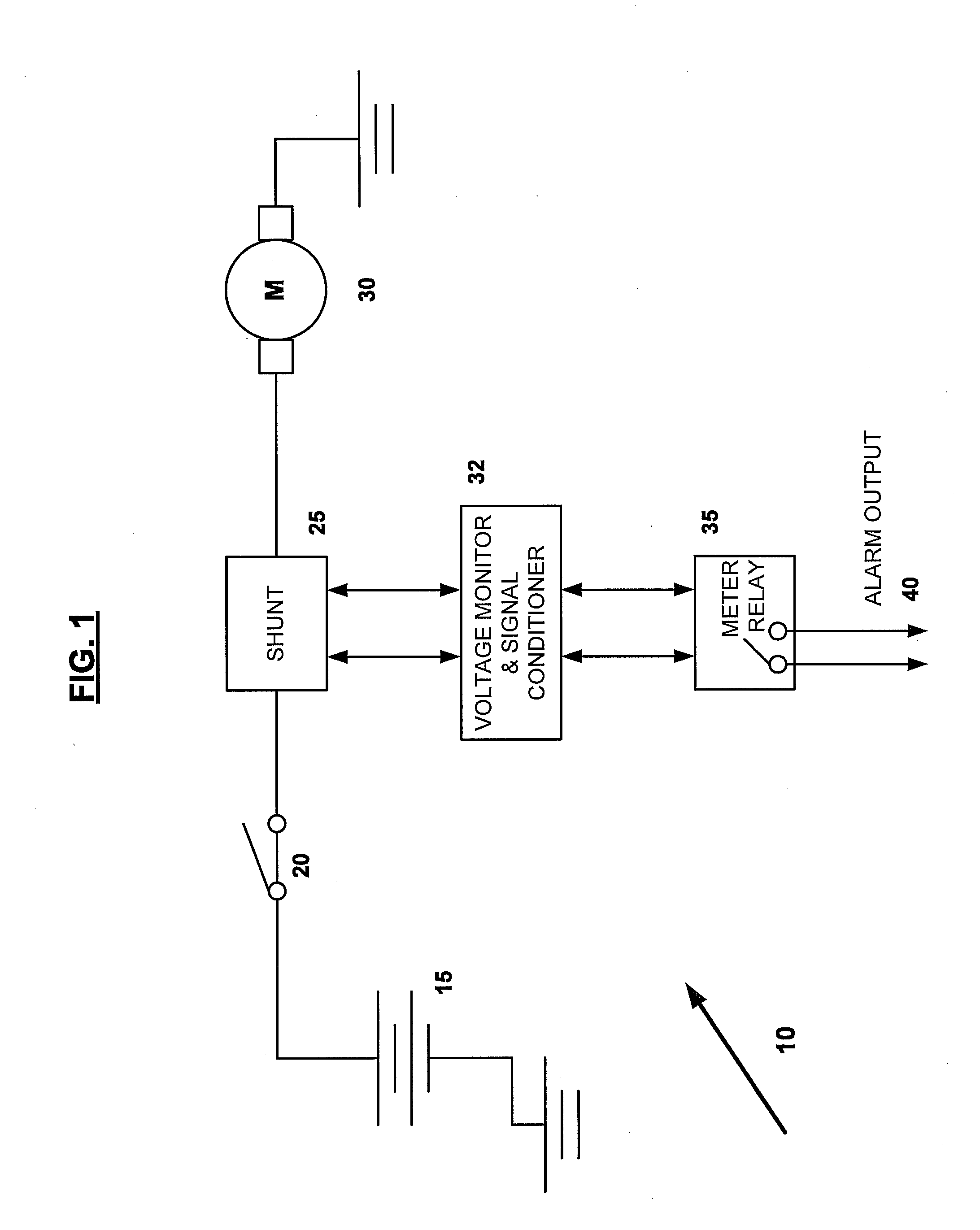
[0032]Turning then to FIG. 1, there is shown a circuit diagram 10 utilizing a conventional shunt and meter relay within the system of the present invention.

[0033]The starting...


PUM


Abstract

The present invention is a method and system for monitoring the continuous flow of power delivered by multiple DC Direct current operated starter motors used to start engine driven electrical generators. The method and system comprise the closing of a starter battery system and an associated starter control switch, causing the starter battery system to discharge through a shunt whereby current is fed into a starter motor. The shunt is optionally provided as a precision resistor with a pre-calibrated voltage drop in millivolts DC proportional to a current passing through it. The shunt directs current to a meter relay, which is calibrated by establishing two set points, or desired trigger ranges, for the meter relay. If the current falls outside a range established by the two set points, then a meter relay alarm output is activated; and, if the current remains within the range, then the meter relay alarm output is not activated. The meter relay alarm output is, optionally, a dry contact which activates a signal device.

Description

CROSS REFERENCE TO RELATED APPLICATIONS[0001]This application claims priority from U.S. Provisional Patent Application Ser. No. 61 / 173,415, filed Apr. 28, 2009, the entire contents of which is herein incorporated fully by reference.FIGURE FOR PUBLICATION[0002]To be selected.BACKGROUND OF THE INVENTION[0003]1. Field of the Invention[0004]The present invention relates to a system for monitoring and testing the secure operation of power generators and related power supply systems. More specifically, the present invention relates to a system for ensuring the continuous flow of power delivered to multiple direct current (DC) operated starter motors where these are used to start a prime mover of an electrical generator such as a reciprocating engine or a turbine engine and to minimize starter motor failure or non-scheduled down-time.[0005]2. Description of the Related Art[0006]Industry and commerce has been, and continues to be, powered by a growing supply of large engine-driven electrica...

Claims


Application Information

Patent Timeline
IPC IPC(8): G01R1/20G01R21/06G06F19/00
CPCG01R31/34G01R19/1659
Inventor FORTNER, DOUGLAS C.
Owner DARBY GROUP
Learn More