
Tube-type or channel-type LED lighting apparatus

a technology of led lighting and tubes, applied in the direction of lighting and heating apparatus, point-like light sources, semiconductor devices for light sources, etc., can solve the problems of limited light color range, poor durability, short life span, etc., and achieve the effect of broadening the angular distribution of emitted light and reducing light loss

Inactive Publication Date: 2010-10-21
SEOUL SEMICONDUCTOR
View PDF7 Cites 42 Cited by
  • Summary
  • Abstract
  • Description
  • Claims
  • Application Information

AI Technical Summary

Benefits of technology

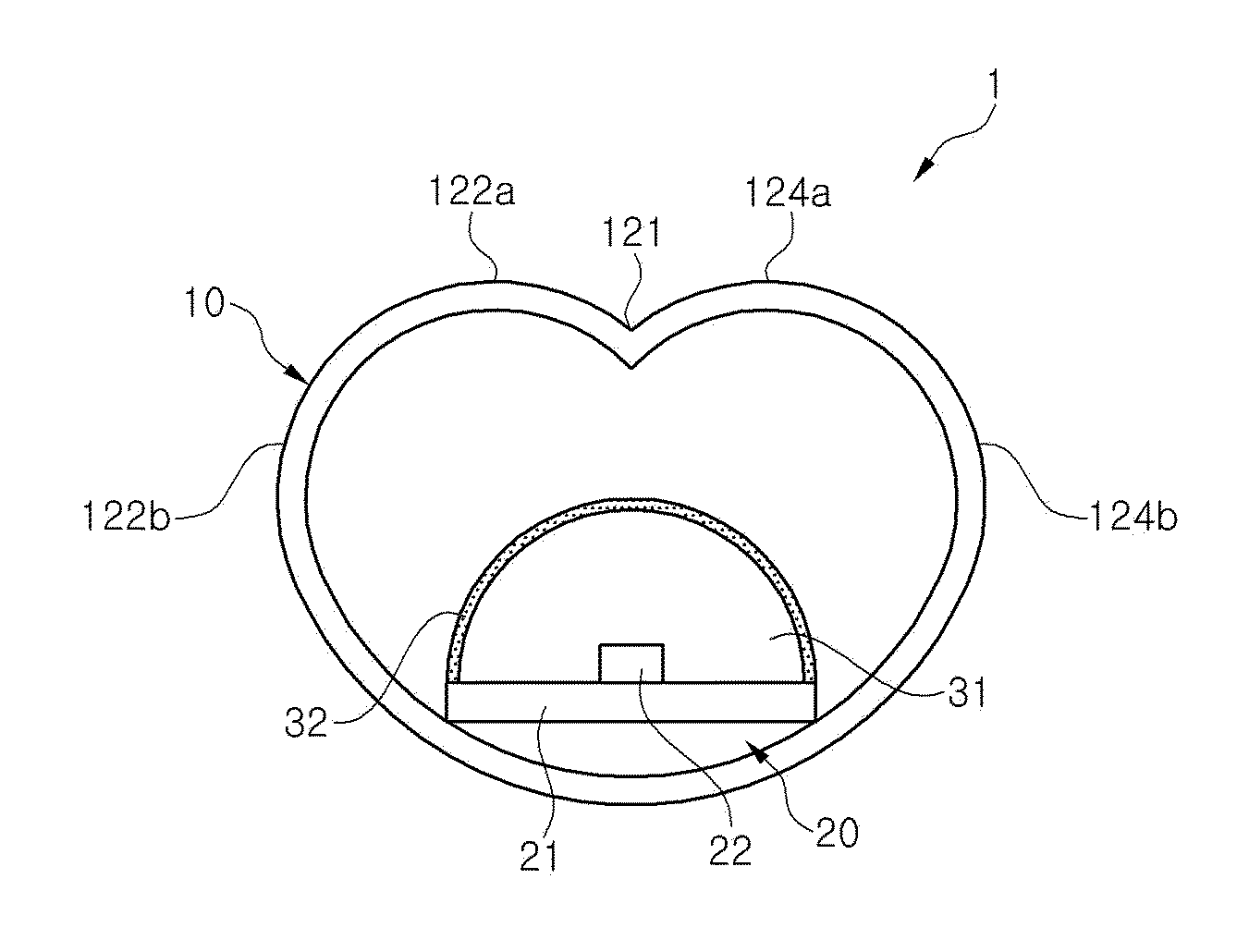
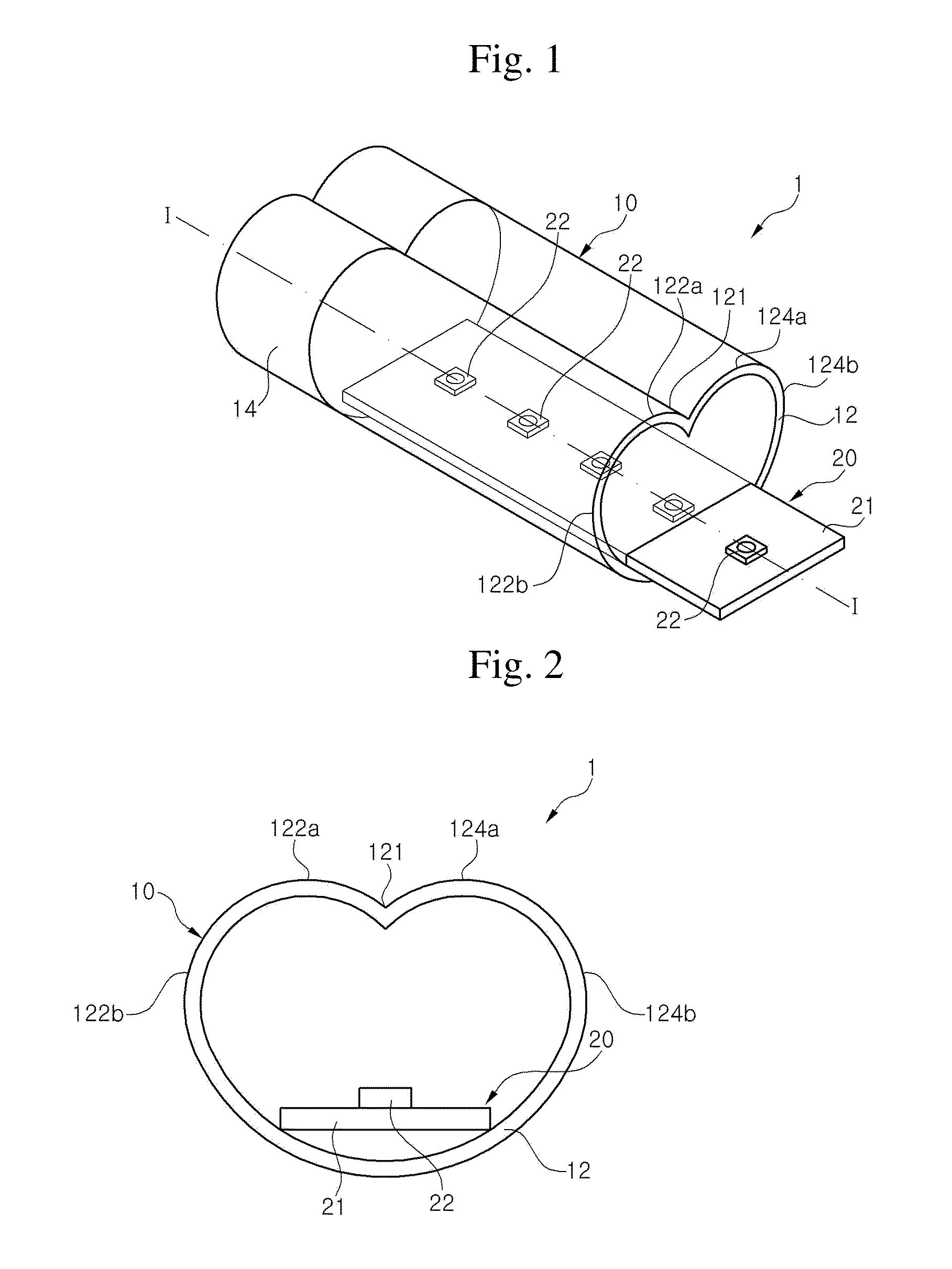
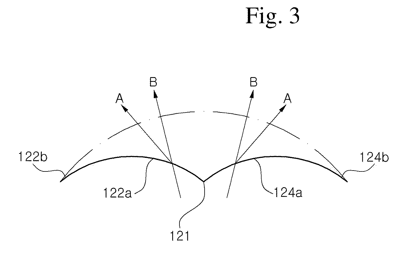
[0010]Exemplary embodiments of the present invention provide a tube-type or channel-type light emitting diode (LED) lighting apparatus capable of reducing light losses while broadening the angular distribution of emitted light, which typically is distributed in a narrow angular range near the central region of the tube or cavity above the LED.
[0011]Exemplary embodiments of the present invention also provide a tube-type or channel-type LED lighting apparatus in which a phosphor is spaced far from an LED in order to decrease the degradation of the phosphor in the LED lighting apparatus. The phosphor would otherwise be included in the LED, particularly in an LED package article.

Problems solved by technology

However, the cold cathode fluorescent lamp may have disadvantages such as a short life span, poor durability, limited range of light colors, and low energy efficiency.
However, the conventional tube-type LED lighting apparatus also may be disadvantageous due to intrinsic characteristics of the LEDs used as a light source.
Accordingly, the conventional tube-type LED lighting apparatus may have many technical limits for replacing the conventional cold cathode fluorescent lamp when used for interior lighting.
Due to the narrow angular distribution of light emission from an LED from its flat light emissive surface, the above channel-type LED lighting apparatus may be subject to serious light losses caused by the internal reflection of the channel, and such apparatus have been used chiefly as advertisement lighting for displaying letters, numerals, marks, logos, and symbols instead of lighting for brightening and illuminating interior spaces.
Even for channel-type LED lighting apparatus used in advertisement lighting, the low light efficiency of the channel-type LED lighting apparatus may be a drawback.
However, as the operating on-time of the LED lighting apparatus increases, the phosphor located adjacent to the LED chip in the LED package article may degrade, thereby lowering the reliability of the LED lighting apparatus.

Method used


Image

  • Tube-type or channel-type LED lighting apparatus
  • Tube-type or channel-type LED lighting apparatus
  • Tube-type or channel-type LED lighting apparatus

Examples


Embodiment Construction

[0027]The invention is described more fully hereinafter with reference to the accompanying drawings, in which embodiments of the invention are shown. This invention may, however, be embodied in many different forms and should not be construed as limited to the embodiments set forth herein. Rather, these embodiments are provided so that this disclosure is thorough, and will fully convey the scope of the invention to those skilled in the art. In the drawings, the size and relative sizes of layers and regions may be exaggerated for clarity. Like reference numerals in the drawings denote like elements.

[0028]It will be understood that when an element or layer is referred to as being “on” or “connected to” another element or layer, it can be directly on or directly connected to the other element or layer, or intervening elements or layers may be present. In contrast, when an element is referred to as being “directly on” or “directly connected to” another element or layer, there are no int...


PUM


Abstract

A light emitting diode (LED) lighting apparatus that may be used as interior lighting or advertisement lighting is disclosed. The LED lighting apparatus includes a channel-type or tube-type optical housing with a light emission surface and an LED array arranged in the optical housing. The light emission surface includes a valley line and a first inner ridge and a second inner ridge disposed on opposing sides of the valley line, and the LED array includes a plurality of LEDs whose centers are arranged along the valley line.

Description

CROSS REFERENCE TO RELATED APPLICATION[0001]This application claims priority from and the benefit of Korean Patent Application No. 10-2009-0027245, filed on Mar. 31, 2009, which is hereby incorporated by reference for all purposes as if fully set forth hereinBACKGROUND OF THE INVENTION[0002]1. Field of the Invention[0003]Exemplary embodiments of the present invention relate to a light emitting diode (LED) lighting apparatus using LEDs and, more particularly, to an LED lighting apparatus having a tube-type or channel-type optical housing.[0004]2. Discussion of the Background[0005]For a long time, a cold cathode fluorescent lamp, referred to as a “fluorescent lamp,” has been used as a lighting apparatus for brightening and illuminating interior spaces in commercial buildings, houses, and interior spaces in transportation means such as airplanes, automobiles, ships, trains, and subway trains. However, the cold cathode fluorescent lamp may have disadvantages such as a short life span, p...

Claims


Application Information

Patent Timeline
Patent Type & Authority Applications(United States)
IPC IPC(8): F21V9/16F21V1/00
CPCF21V5/04F21Y2103/003F21Y2101/02F21Y2103/006F21Y2103/10F21Y2103/30F21Y2115/10F21Y2115/20F21V15/01F21V23/001F21K9/20
Inventor RYU, SEUNG RYEOLBAE, SANG GEUNHONG, SEUNG SIKPARK, KWANG IL
Owner SEOUL SEMICONDUCTOR
Learn More