
Antenna Assembly

a technology of antenna equipment and assembly, which is applied in the manufacture of antenna arrays, antennas, antenna details, etc., can solve the problems of increasing the coverage and capacity of cellular telephone systems, difficult to position antenna equipment at less visible, and little possibility of hiding antenna equipmen

Active Publication Date: 2010-10-21
INTEL CORP
View PDF9 Cites 32 Cited by
  • Summary
  • Abstract
  • Description
  • Claims
  • Application Information

AI Technical Summary

Benefits of technology

[0010]It is an object of the present invention to provide a manufacturing method for manufacturing antenna assemblies comprising a plurality of antenna arrays that at least mitigates the above mentioned problems.
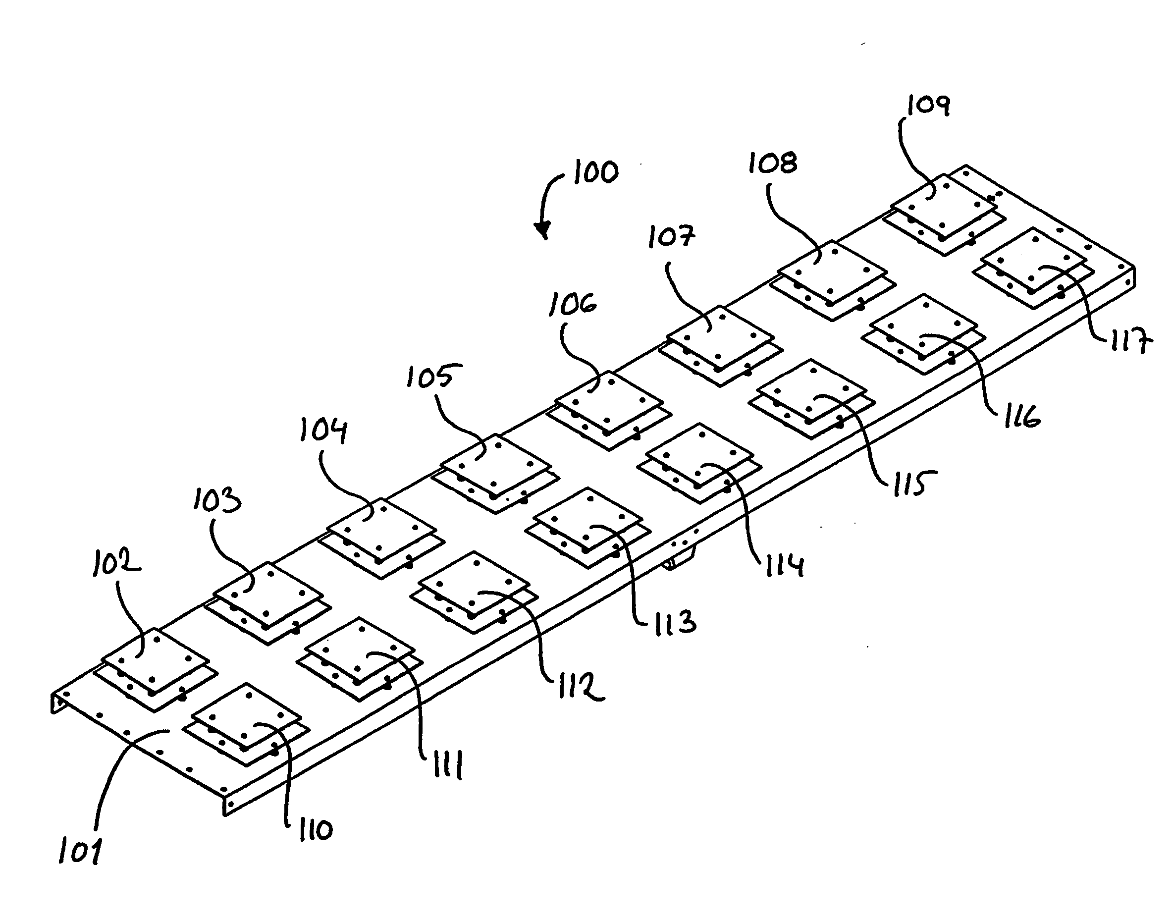
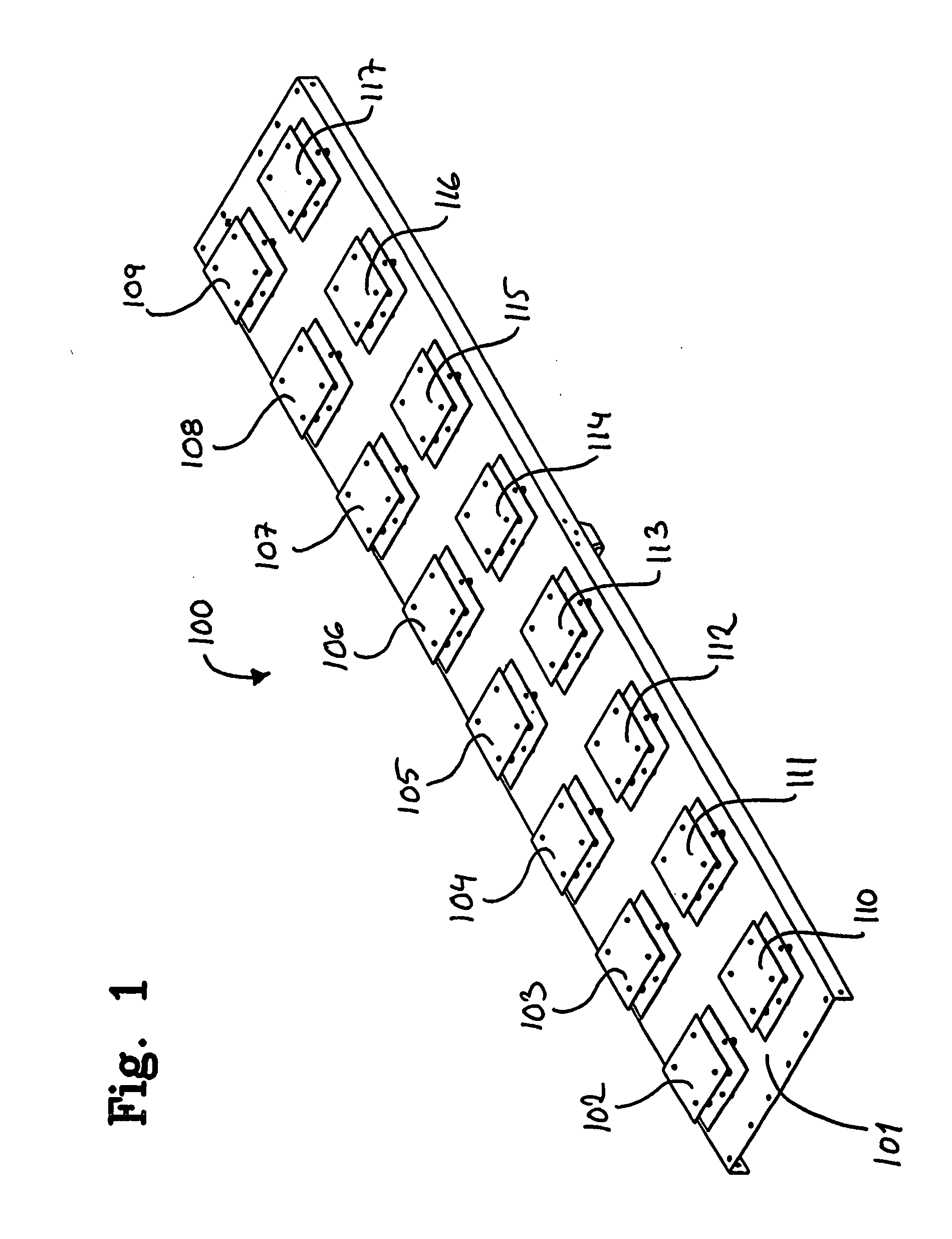
[0014]This has the advantage that torsional rigidity of the antenna assembly can be substantially improved as compared to prior art solutions, since the additional center wall formed by the side portions of the assembly portions will have a substantial effect on the torsional rigidity in a positive manner. Further, the invention also has the advantage that the number of antenna assembly variants that has to be manufactured can be kept to a minimum.

Problems solved by technology

The use of cellular telephone systems is constantly increasing, which, in turn, imposes increasing demands on the coverage and capacity of the cellular telephone systems.
These units all require physical space and also often interconnection by means of cables.
This makes cell site planning a challenge from an aesthetic point of view, and often gives rise to conflicts with environmentalists and owners of buildings and other locations at which the cell sites are to be located.
With regard to cell sites comprising masts, these masts are often of a framework kind, with little possibilities of hiding the antenna equipment.
The constantly increasing demands with regard to communication capacity will also result in more and more cell sites, thus rendering it even more difficult to position the antenna equipment at less visible and thereby aesthetically less disturbing locations.
However, such integration attempts can also give rise to other more negative effects, e.g. with regard to the manufacturing process.

Method used


Image

  • Antenna Assembly
  • Antenna Assembly
  • Antenna Assembly

Examples


Embodiment Construction

[0022]The demand for antennas for mobile wireless applications has increased dramatically, and today there exist a number of various radio access technologies for providing wireless communication. A wide range of frequency bands has been allocated, and is being used, for the various existing kinds of wireless communication, and for providing communication in a plurality of frequency bands, also within one single radio access technology.

[0023]When older wireless communication systems are being replaced in favour of newer technology, the frequency resources of the older system are in general reused, since the increasing demands on wireless communication makes efficient utilization of existing frequency bands increasingly important.

[0024]Even so, it is also common that two or more radio access technologies co-exist and utilize at least partially overlapping frequency bands, e.g. older and newer generation radio access technologies, or radio access technologies being intended for differ...


PUM

PropertyMeasurementUnit
Shapeaaaaaaaaaa
Electrical conductoraaaaaaaaaa
Mechanical propertiesaaaaaaaaaa

Abstract

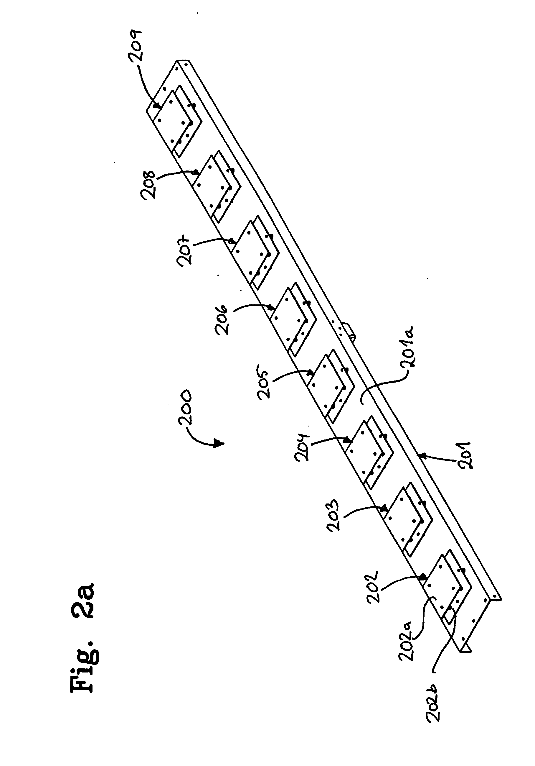
An antenna assembly and a method of mounting such an assembly are disclosed. A first and a second assembly portion are joined together, wherein the assembly portions each comprise a elongated reflector body serving as a reflector for electromagnetic power radiated by the antenna assembly portion, and a set of antenna element receiving means located in a linear row along a longitudinal direction of the reflector body for respectively receiving an antenna element, and side portions along the long sides of the said reflector body. The assembly method comprises the step of fastening the first and second assembly portions to each other along a respective side portion of the said assembly portions so as to form a dual array antenna assembly.

Description

RELATED APPLICATION INFORMATION[0001]The present application claims priority under 35 U.S.C. Section 119(e) to U.S. provisional patent application No. 61 / 170,204 filed on Apr. 17, 2009, the disclosure of which is incorporated herein by reference in its entirety.FIELD OF THE INVENTION[0002]The present invention relates to antenna assemblies and methods of manufacturing such assemblies.BACKGROUND OF THE INVENTION[0003]The use of cellular telephone systems is constantly increasing, which, in turn, imposes increasing demands on the coverage and capacity of the cellular telephone systems.[0004]Cellular telephone system coverage and capacity, however, is largely dependent on the antennas being used, and the locations of the antennas, which ultimately has an impact on the number of antennas / antenna sites that are required to provide the desired network coverage and capacity.[0005]A conventional cell site often has a number of physical units. Firstly, the site comprises the actual antenna, ...

Claims


Application Information

Patent Timeline
IPC IPC(8): H01Q19/10H01P11/00
CPCH01Q1/246Y10T29/49016H01Q21/065H01Q19/10H01Q21/0087
Inventor ARVIDSSON, PER-ANDERSARIAS, MARIOBEAUSANG, MICHAELUDDIN, JESPERHU, ANNIKA
Owner INTEL CORP
Learn More