Magnet Core; Method for Its Production and Residual Current Device

Inactive Publication Date: 2010-10-21
VACUUMSCHMELZE GMBH & CO KG
View PDF8 Cites 15 Cited by
  • Summary
  • Abstract
  • Description
  • Claims
  • Application Information

AI Technical Summary

Benefits of technology

[0009]Accordingly, there remains a need to devise a magnet core that is wound from a magnetically soft band that is effectively protected against externally applied mechanical stresses and thus has permanently good magnetic properties.

Problems solved by technology

However, it is only possible to easily achieve such a small saturation magnetostriction constant λs with only a few alloys.
Moreover, for industrial production, it is almost impossible to achieve a sufficiently exact alloy composition without impurities.
This process cannot, however, be transferred to a magnet core made of a magnetostrictive alloy since before complete crosslinking of silicone cement, it creeps as a result of capillary forces and the inherent weight of the magnet core between the band layers of the magnet core.
Since the intensity of penetration of the silicone cement between the band layers depends largely on randomly occurring defects of form, this effect can, moreover, only be predicted with difficulty and leads to serious variance of the permeability values.
As a result, tensile forces caused by shrinking of the volume of the cement necessarily deliver mechanical stresses into the magnet core.
A nonpositive connection between the magnet core and protective housing would result in differences in thermal expansion between the material of the magnet core and that of the housing, which make themselves noticeable directly by mechanical deformations.
between the relative permeability μr, the saturation magnetostriction constant λs and the mechanical stress σ, these deformations lead to overly small and, moreover, highly varying relative permeabilities when the saturation magnetostriction constant is not small enough.

Method used


Image

  • Magnet Core; Method for Its Production and Residual Current Device
  • Magnet Core; Method for Its Production and Residual Current Device
  • Magnet Core; Method for Its Production and Residual Current Device

Examples


Embodiment Construction

[0022]In one advantageous embodiment, the contact cement has an acrylate polymer. Compared to other fundamentally suitable contact cement masses such as, for example, based on rubber, polyvinyl ester, polybutadiene or polyurethane, those based on acrylate polymers have the advantage that they allow the formulation of especially resistant cement masses.

[0023]In one advantageous embodiment, the contact cement has an elongation at tear, εR, such that εR>250%, preferably >450%, furthermore preferably >600%. These contact cements are relatively elastic in order to prevent unwanted force transfer between the housing and the magnet core that has been fixed in it. Furthermore, the contact cement advantageously has a glass transition temperature Tg, such that Tgggs such that Ts>180° C.

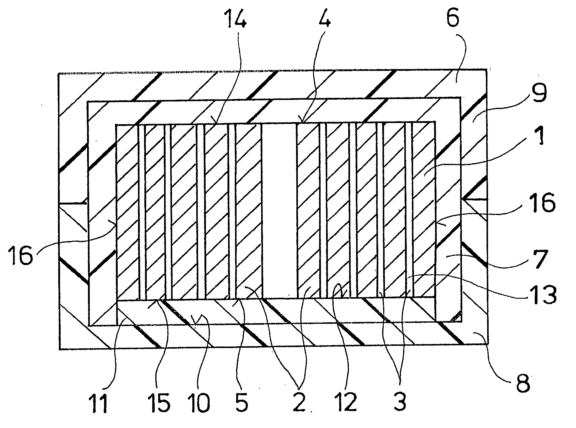
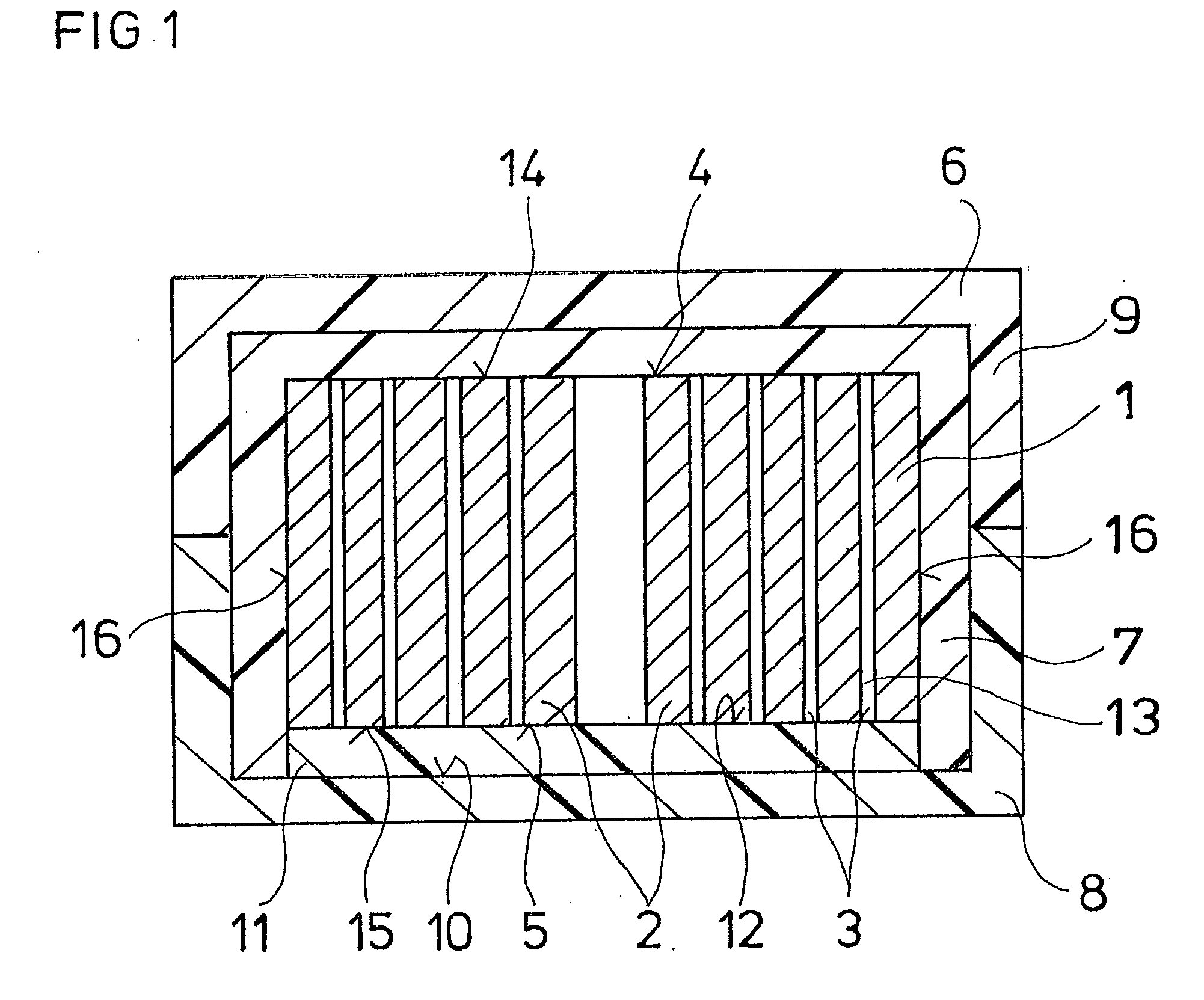
[0024]The penetration depth t of the contact cement between the band layers of the magnet core in one advantageous embodiment is t<2 mm, preferably t<0.5 mm and, furthermore, preferably t<0.01 mm.

[0025]Typicall...


PUM

PropertyMeasurementUnit
Temperatureaaaaaaaaaa
Percent by massaaaaaaaaaa
Magnetic fieldaaaaaaaaaa

Abstract

A magnet core (1) that is suitable for use in a fault current circuit breaker and that is made of a helically wound, magnetically soft band has a top (4) and a bottom (5), the top (4) and the bottom (5) being formed by side surfaces (16) of the magnetically soft band. The magnet core (1) is fixed in a protective housing (6), and there is a contact cement (11) between the bottom (5) of the magnet core (1) and an inside wall (10) of the housing for fixing the magnet core (1).

Description

BACKGROUND[0001]1. Field[0002]Disclosed herein is a magnet core that is wound from a magnetically soft band. Also disclosed is to a method for producing such a magnet core and a fault current circuit breaker with a magnet core.[0003]2. Description of Related Art[0004]Magnet cores that are formed from a helically wound metal band, so-called ring band cores, are used in, for example, current transformers, power transformers, current-compensated radio interference suppression reactors, starting current limiters, storage reactors, single-conductor reactors, half-cycle transductors, and sum or difference current transformers for FI circuit breakers.[0005]High demands are imposed on these cores with respect to magnetic properties: fault current transformers for AC-sensitive fault current circuit breakers, for example, must make available a secondary voltage that is at least enough to trigger the magnet system of the trigger relay that is responsible for shut-off. Since a design of a curre...

Claims


Application Information

Patent Timeline
IPC IPC(8): H01H50/00H01F27/24H01F41/02
CPCH01F3/04H01F27/25H01F27/266Y10T29/49075H01F2038/305H01F1/15333H01F41/0213
Inventor PETZOLD, JOERGBRUNNER, MARKUS
Owner VACUUMSCHMELZE GMBH & CO KG
Why Eureka
Try Eureka