Apparatus and method for simulating lifetime of and/or stress experienced by a rotor blade and rotor disc fixture

a technology of rotor disc fixture and lifetime simulation, which is applied in the direction of instrumentation, gas turbine engine testing, structural/machine measurement, etc., can solve the problems of difficult to test the root of the blade under conditions representative of the operating conditions of the gas turbine engine, not always giving a correct estimate of lcf, and difficult to test the whole blade stati

Active Publication Date: 2010-10-21
ROLLS ROYCE PLC
View PDF16 Cites 19 Cited by
  • Summary
  • Abstract
  • Description
  • Claims
  • Application Information

AI Technical Summary

Benefits of technology

[0008]A blade specimen may be mounted to the mounting member and a tension load applied in order to simulate the operation stress experienced by the blade. The gap between the contacting regions and the main body of the block enables the blade contacting regions to deflect outward in a way which simulates the strain (change of shape) of the rotor disc when rotating in operating conditions.
[0010]The blade specimen may simulate a whole rotor blade across its chord, or a section or slice of a rotor blade. It may be convenient to select a slice of the rotor blade which experiences maximum stress during operation and make blade specimen corresponding to said slice of the blade. By simulating only a slice, it is possible to reduce the force applied by the actuator while still achieving the desired stress conditions.
[0018]A second aspect of the present invention provides a method of simulating the stresses experienced by a mounting arrangement of a rotor blade in a rotor disc, comprising the steps of placing a blade specimen having a root in a mounting member for receiving the blade specimen, said mounting member having an aperture for receiving the root of the blade specimen, and blade contacting regions on either side of said aperture for holding said blade specimen in said aperture, said blade contacting regions being undercut such that there is a gap between said blade contacting regions and a main body of said mounting member, whereby the blade contacting regions are able to deflect outward into said gap (and towards the main body) when a tension load is applied to said blade specimen; and using an actuator to apply a tension load to said blade specimen.
[0026]The apparatus may have first and second opposing structural members, preferably in the form of plates. The blade mounting member may be mounted to the first structural member either directly or indirectly (eg via a movable rack which is mounted to the first structural member). The blade mounting member is preferably movable in a plane substantially parallel to the plane of the first structural member. The blade attachment member may be supported by the second structural member, eg it may be attachable (directly or indirectly) to an actuator which is mounted to the second structural member. This makes it easy to adjust the lean of the blade by moving the blade mounting member back and forth in a line parallel to faces of the blade specimen when it is mounted in the blade mounting member. For example, the blade mounting member may be mounted to the first structural member via one or more rails or recesses and movable along said rails or recesses. The blade mounting member may be movable relative to the first structural member in one direction (eg along the y axis) or in two directions (eg along the x and y axes). The twist of the blade specimen may be adjusted by a combination of displacement in the x and y directions. The position may be temporarily fixable by locking the blade mounting member in place. Preferably the way in which the blade attachment member is supported by the second structural member or actuator provides a degree of play to allow a desired level of non axi-symmetric loading.
[0033]A fourth aspect of the present invention provides a method of simulating the axial and radial stresses experienced by the root and shank of a rotor blade when the rotor blade is in operation; the method comprising the steps of: providing a blade mounting member adapted to receive and hold the root of a blade specimen; providing a blade attachment member which is adapted for attachment to the wing of a blade specimen; mounting the root of a blade specimen in the blade mounting member and attaching a wing of the blade specimen to the blade attachment member; adjusting the relative positioning of the blade mounting member and the blade attachment member in order to achieve a desired lean and twist of said blade specimen, and using an actuator to apply a force to the first and / or second structural member so as to apply a tension load to said blade specimen.

Problems solved by technology

However, because of the large and variable forces involved, it is difficult to test a blade root under conditions representative of the operating conditions in a gas turbine engine.
Long tests are undesirable and can result in the inability to carry out testing of multiple design options, which have the potential to result in design improvements.
However, although slice testing is useful it does not always give a correct estimate of the LCF as the slice does not give the same readings as that of a whole blade in operation.
On the other hand, whole blade static testing is difficult as there is a need to apply many tens of tonnes of force (30 to 60 being typical) to give a representative loading under operation.
There is a difficulty in applying sufficient force to the whole blade and difficulty in applying sideways or non-axial loads.

Method used


Image

  • Apparatus and method for simulating lifetime of and/or stress experienced by a rotor blade and rotor disc fixture
  • Apparatus and method for simulating lifetime of and/or stress experienced by a rotor blade and rotor disc fixture
  • Apparatus and method for simulating lifetime of and/or stress experienced by a rotor blade and rotor disc fixture

Examples


first embodiment

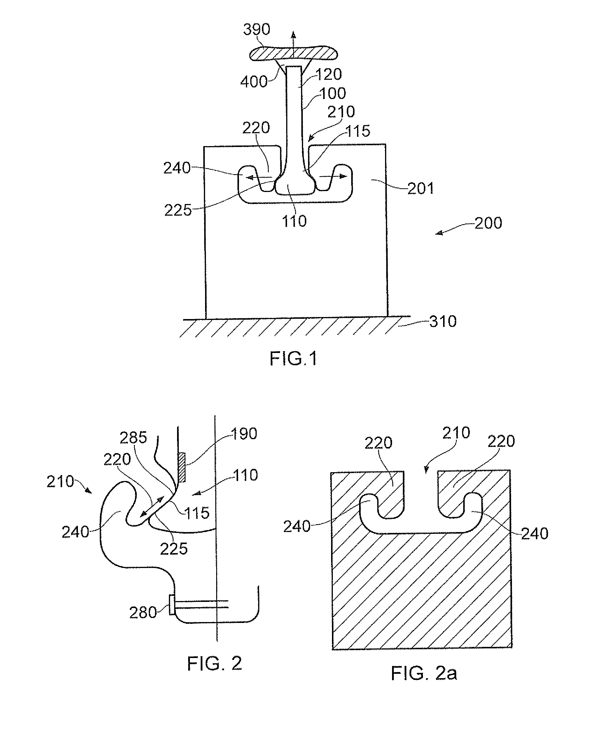
[0053]An apparatus and method for simulating the stresses experienced by and / or the life of a mounting arrangement of a rotor blade in a rotor disc will now be described. The mounting arrangement refers to the features attaching the blade root to the rotor disc and includes both the root of the blade and the mounting features of the rotor disk. The method and apparatus will be particularly useful for simulating a blade mounting arrangement in a gas turbine engine. However it may be used to simulate blade mounting arrangements in any suitable apparatus with rotating blades, eg a compressor, a turbine, a rotor craft, or wind turbine.

[0054]In the present embodiment the root of the rotor blade under investigation forms a dovetail fit with the rotor disc. However arrangements with other friction fits, eg a fir tree root arrangement, could also be simulated.

[0055]The apparatus is used to simulate the rotor blade root region stress distribution, displacements and slip generated by the cycl...

second embodiment

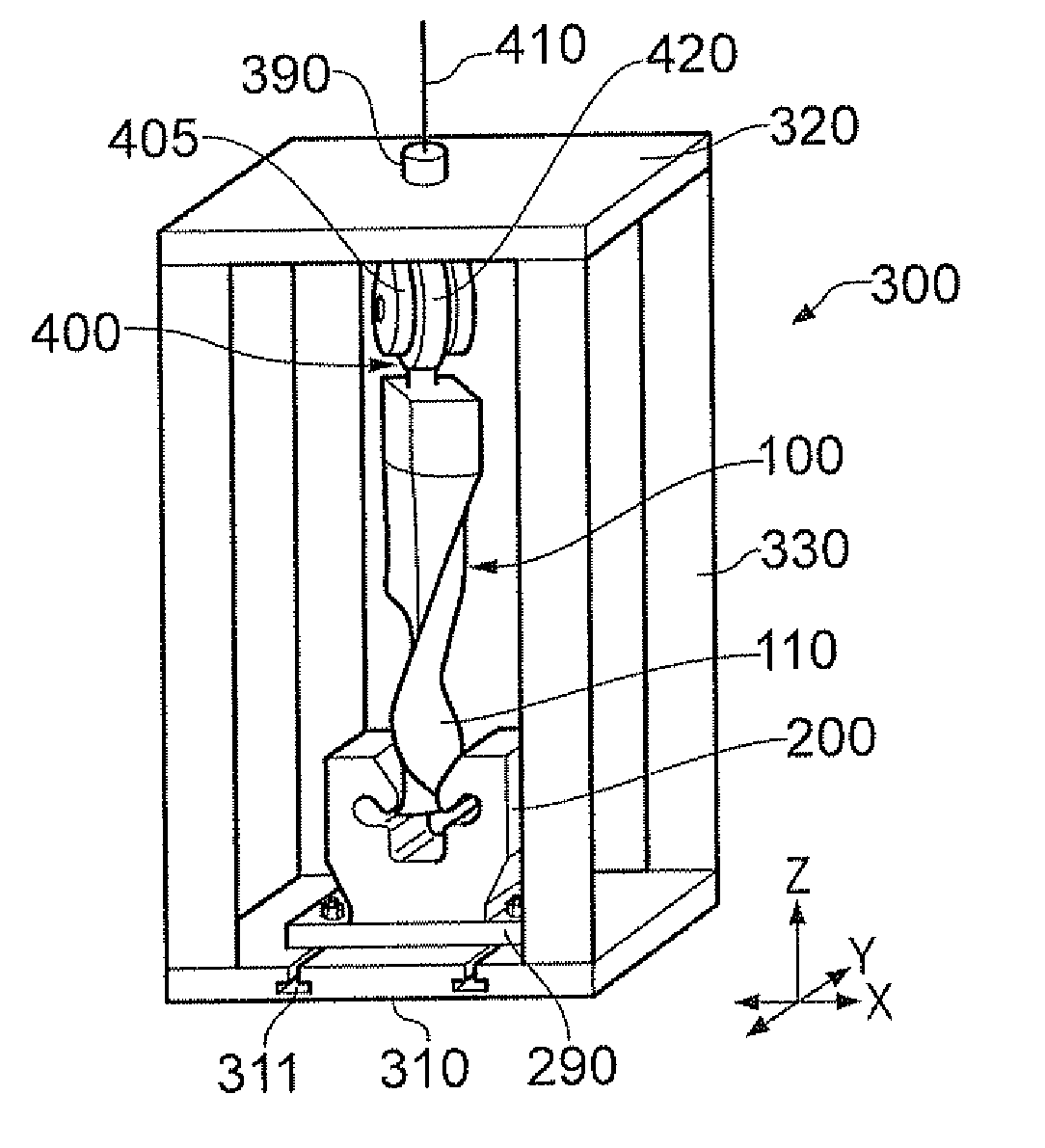
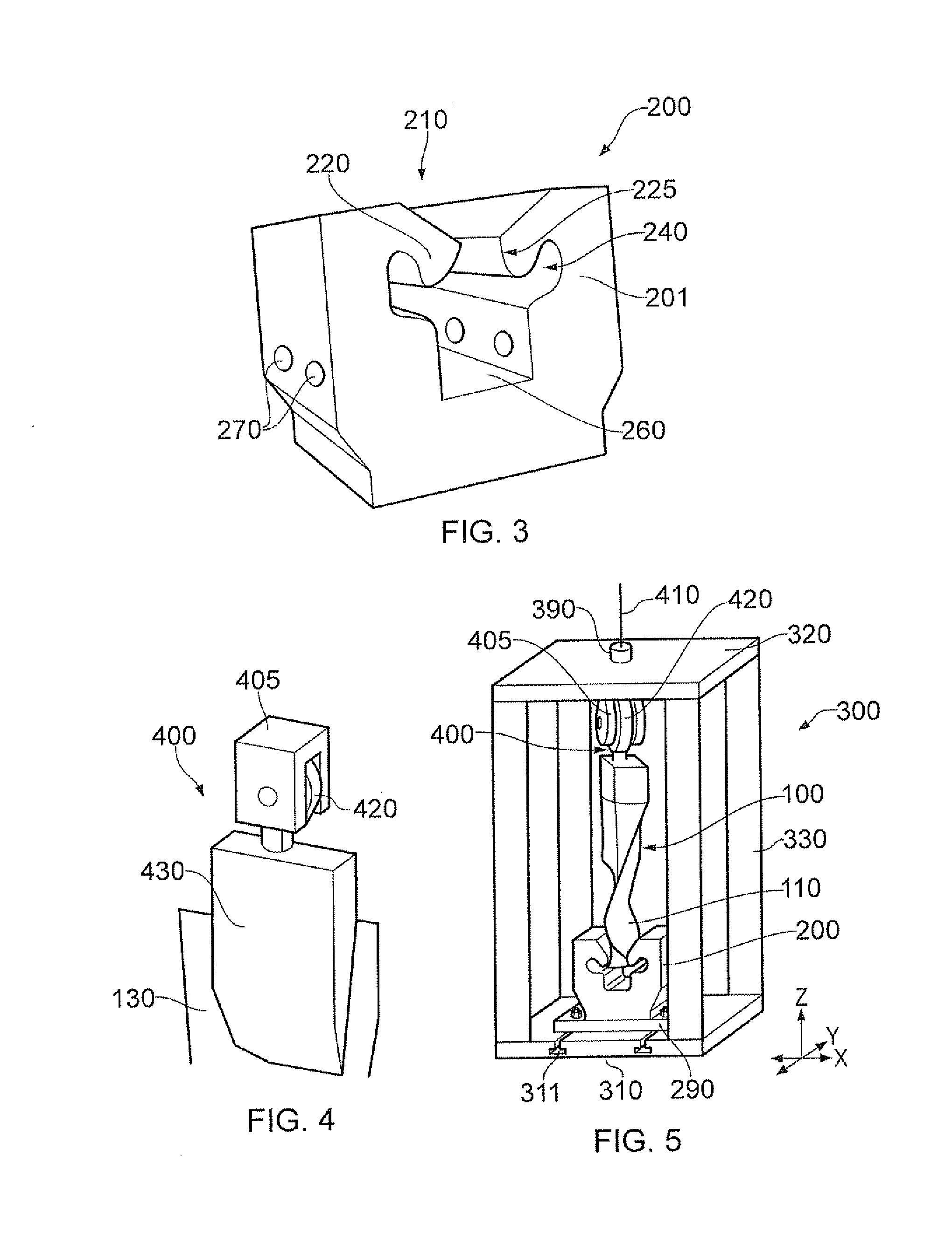
[0070]FIGS. 3 to 5 show an apparatus which may be used for testing a rotor blade specimen in a static fatigue rig. The apparatus is able to replicate the displacement and stresses in the root and shank region of the blade both in the radial and axial directions.

[0071]A blade mounting member 200 is designed to reproduce the root (eg dovetail) contact and shank stresses, slip and displacement observed in the simulated rotor blade and rotor disc mounting arrangement in operational conditions (eg those in a turbine engine under centripetal loading). A tension load simulating the centripetal load is applied to the rotor blade specimen 100 through a blade attachment member 400 attached to the wing (eg the aerofoil region) of the blade specimen. The tension load is applied in a way that allows non axi-symmetric loading and so the introduction of blade lean and twist. Lean and twist are required to replicate the change in blade shape under the centripetal loading and steady aerodynamic forc...


PUM

PropertyMeasurementUnit
tensionaaaaaaaaaa
stiffnessaaaaaaaaaa
forceaaaaaaaaaa

Abstract

An apparatus for simulating stresses experienced by a rotor blade root in a complementary disc fixture, especially in gas turbine engines. The apparatus comprises a mounting member for receiving a blade speciman having a root. The mounting member has an aperture for receiving the root of the blade specimen, and blade contacting regions on either side of said aperture for holding said blade specimen in said aperture. The apparatus further comprises an actuator for applying a tension load to said blade specimen. The blade contacting regions are undercut such that there is a gap between said blade contacting regions and a main body of said mounting member, whereby the blade contacting regions are able to deflect outward into said gap when a tension load is applied to the blade specimen.

Description

FIELD OF THE INVENTION [0001]The present invention relates to fatigue testing of materials and more particularly relates to an apparatus and method for simulating fatigue of rotor blade roots in complementary rotor blade slots. The method and apparatus may simulate the lifetime of, and stresses experienced by, a rotor blade and rotor disc fixture. The invention will find particular application to rotor blade and disc fixtures in a gas turbine engine, but may also be applied to other apparatus with rotating blades. For example, it may be used to simulate blade fixing arrangements in a compressor, a turbine, a rotor craft, a wind turbine or windmill.[0002]It is necessary to fatigue test the fixing arrangement of the rotor blade to ensure that its operational lifetime and resistance to stress meets the desired requirements. However, because of the large and variable forces involved, it is difficult to test a blade root under conditions representative of the operating conditions in a ga...

Claims


Application Information

Patent Timeline
Patent Type & Authority Applications(United States)
IPC IPC(8): G01N3/08
CPCG01N3/04G01N3/32G01N2203/0435G01N2203/0246G01N2203/0226G01M5/0016G01M5/005G01M15/14
Inventor MASON, PAUL J.
Owner ROLLS ROYCE PLC
Why Eureka
Try Eureka