Method and apparatus for distracting a joint

a technology for distracting joints and joints, applied in the field of surgical methods and equipment, can solve the problems of significant interference with patient comfort and lifestyle, pathology so severe as to require partial or total hip replacement, and the scope of procedures is generally limited, so as to maintain the distraction of a joint, minimize the damage to intervening tissue, and distract a joint

Active Publication Date: 2012-09-20
STRYKER CORP
View PDF2 Cites 21 Cited by
  • Summary
  • Abstract
  • Description
  • Claims
  • Application Information

AI Technical Summary

Benefits of technology

[0041]Among other things, the present invention provides a novel method for distracting a joint and for maintaining distraction of a joint, wherein the novel method minimizes damage to intervening tissue while maintaining distraction of the joint. In addition, the novel method allows visualization of areas in the hip joint that were not previously visible using a conventional hip distraction approach.
[0047]reducing the force applied to the body part so that the joint is supported on the at least one balloon, with the two bones remaining separated from one another by a distance which is greater than the distance that they are normally separated from one another when the joint is in a healthy state.

Problems solved by technology

In other cases, the pathology may be minor at the outset but, if left untreated, may worsen over time.
The pathology may, either initially or thereafter, significantly interfere with patient comfort and lifestyle.
In some cases, the pathology can be so severe as to require partial or total hip replacement.
A number of procedures have been developed for treating hip pathologies short of partial or total hip replacement, but these procedures are generally limited in scope due to the significant difficulties associated with treating the hip joint.
In some cases, and looking now at FIG. 13, this impingement can occur due to irregularities in the geometry of the femur.
In other cases, and looking now at FIG. 14, the impingement can occur due to irregularities in the geometry of the acetabular cup.
Impingement can result in a reduced range of motion, substantial pain and, in some cases, significant deterioration of the hip joint.
Defects of this type sometimes start out fairly small but often increase in size over time, generally due to the dynamic nature of the hip joint and also due to the weight-bearing nature of the hip joint.
Articular defects can result in substantial pain, induce and / or exacerbate arthritic conditions and, in some cases, cause significant deterioration of the hip joint.
More particularly, in many cases, an accident or sports-related injury can result in the labrum being torn away from the rim of the acetabular cup, typically with a tear running through the body of the labrum.
These types of injuries can be very painful for the patient and, if left untreated, can lead to substantial deterioration of the hip joint.
Unfortunately, minimally-invasive treatments for pathologies of the hip joint have lagged far behind minimally-invasive treatments for pathologies of the shoulder joint and the knee joint.
As a result, it is relatively difficult for surgeons to perform minimally-invasive procedures on the hip joint.
This limited access further complicates effectively performing minimally-invasive procedures on the hip joint.
In addition to the foregoing, the nature and location of the pathologies of the hip joint also complicate performing minimally-invasive procedures on the hip joint.
This makes drilling into bone, for example, significantly more complicated than where the angle of approach is effectively aligned with the angle at which the instrument addresses the tissue, such as is frequently the case in the shoulder joint.
Furthermore, the working space within the hip joint is typically extremely limited, further complicating repairs where the angle of approach is not aligned with the angle at which the instrument addresses the tissue.
As a result of the foregoing, minimally-invasive hip joint procedures are still relatively difficult to perform and relatively uncommon in practice.
Consequently, patients are typically forced to manage their hip pain for as long as possible, until a resurfacing procedure or a partial or total hip replacement procedure can no longer be avoided.
These procedures are generally then performed as a highly-invasive, open procedure, with all of the disadvantages associated with highly-invasive, open procedures.
However, since the distracting force is applied to the lower end of the patient's leg, this approach necessitates that the distracting force be applied across substantially the entire length of the leg.
In practice, it has been found that the longer the distracting load is maintained on the leg, the greater the trauma imposed on the intervening tissue.
Specifically, it has been found that temporary or even permanent neurological damage can occur if the leg is distracted for too long using conventional distraction techniques.
And even where the duration of the distraction is kept to 90 minutes or less, significant complications can nonetheless occur for many patients.
Unfortunately, it has been found that the use of a perineal post can contribute to the damage done to the intervening tissue when the leg is distracted too long.
Thus, if the distraction is held too long, neurological damage can occur.
Additionally, the perineal post can exert pressure on the blood vessels in the leg, and it has been shown that blood flow in these vessels (e.g., the femoral vein, etc.) may be significantly reduced, or in some cases completely occluded, while the hip is in distraction, thus placing the patient in danger of forming deep vein thrombosis or developing other complications.
Additionally, current hip distraction using an external distraction device limits the extent to which the leg can be manipulated under distraction during hip arthroscopy, since a substantial pulling force must be maintained on the distal end of the leg throughout the duration of the distraction.
Due to this, and due to the fact that there are typically only 2-4 portals available for surgical access into the interior of the hip joint, visualization and access to hip joint pathology and anatomy is frequently hindered while the leg is being externally distracted.
This can limit the extent of surgical procedures available to the surgeon, and can prevent some procedures from being attempted altogether.
Procedures such as mosaicplasty and autologous cartilage injection are examples of procedures which require access to extensive areas of the articular surfaces of the femoral head, but which are typically not performed arthroscopically because of the aforementioned access limitations when the leg is being distracted using an external distraction device.

Method used


Image

  • Method and apparatus for distracting a joint
  • Method and apparatus for distracting a joint
  • Method and apparatus for distracting a joint

Examples


Embodiment Construction

Novel Joint-Spacing Balloon Catheter

[0100]In one form of the present invention, there is provided a novel joint-spacing balloon catheter for use in distracting a joint, and more particularly for maintaining the distraction of a previously-distracted joint, as will hereinafter be discussed in detail.

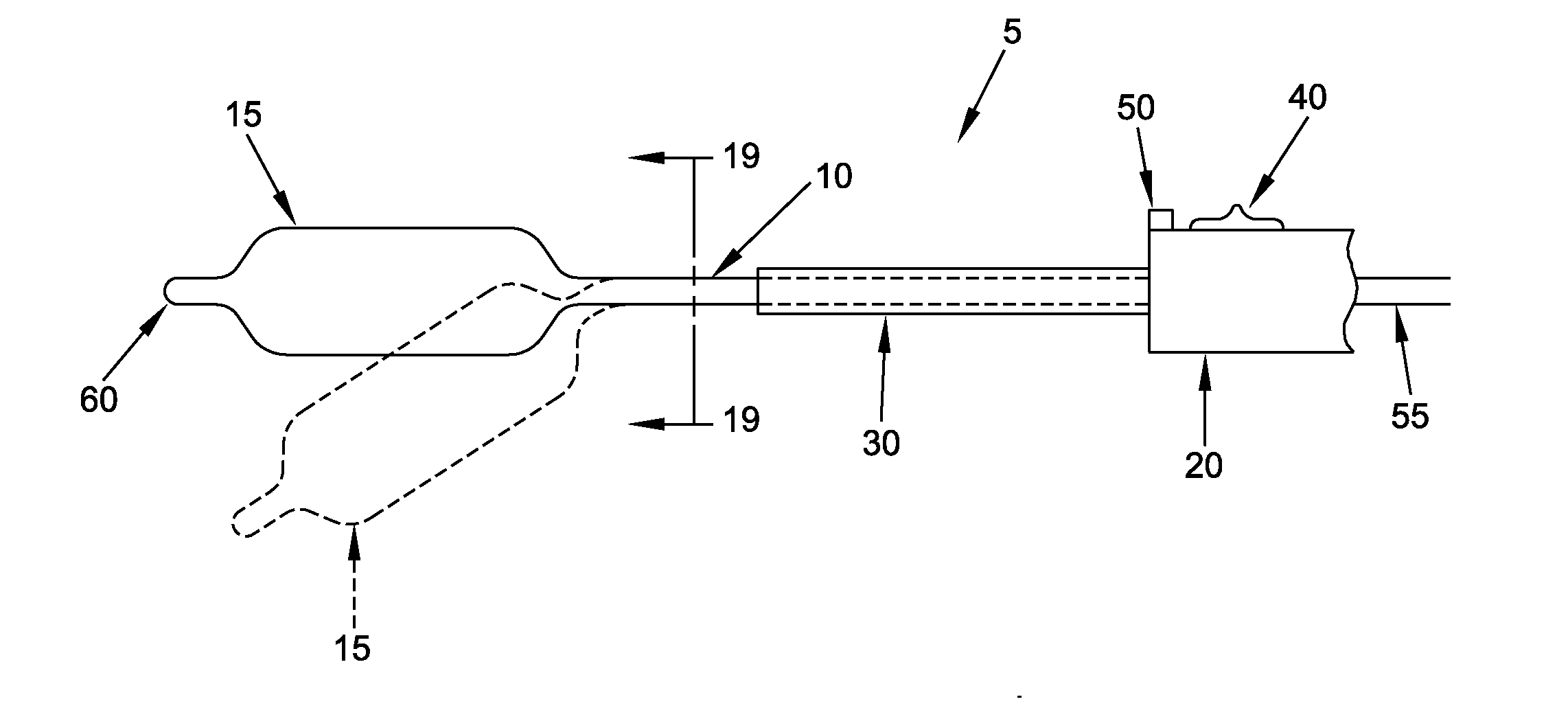
[0101]More particularly, in this form of the invention, and looking next at FIGS. 17-19, there is shown a novel joint-spacing balloon catheter 5 formed in accordance with the present invention. Novel joint-spacing balloon catheter 5 generally comprises an elongated shaft 10 having a balloon 15 disposed at its distal end and a handle 20 disposed at its proximal end. If desired, and as will hereinafter be discussed, multiple balloons 15 may be disposed on the distal end of elongated shaft 10.

[0102]Elongated shaft 10 is preferably flexible, and preferably includes an internal stiffener 25 extending along at least a portion of its length so as to facilitate proper positioning of balloon 15 du...


PUM


Abstract

A joint-spacing balloon catheter comprising:a shaft having a distal end and a proximal end;first and second balloons mounted to the distal end of the shaft, the first balloon being disposed distal to, and spaced from, the second balloon, with the portion of the shaft between the first and second balloons being flexible; anda handle attached to the proximal end of the shaft.

Description

REFERENCE TO PENDING PRIOR PATENT APPLICATIONS[0001]This patent application:[0002](i) is a continuation-in-part of pending prior U.S. patent application Ser. No. 12 / 726,268, filed Mar. 17, 2010 by Julian Nikolchev et al. for METHOD AND APPARATUS FOR DISTRACTING A JOINT, INCLUDING THE PROVISION AND USE OF A NOVEL JOINT-SPACING BALLOON CATHETER AND A NOVEL INFLATABLE PERINEAL POST (Attorney's Docket No. FIAN-28424953), which claims benefit of: (a) prior U.S. Provisional Patent Application Ser. No. 61 / 210,315, filed Mar. 17, 2009 by Julian Nikolchev et al. for JOINT SPACING BALLOON CATHETER (Attorney's Docket No. FIAN-28 PROV); (b) prior U.S. Provisional Patent Application Ser. No. 61 / 268,340, filed Jun. 11, 2009 by Julian Nikolchev et al. for METHOD AND APPARATUS FOR DISTRACTING A JOINT, INCLUDING THE PROVISION AND USE OF A NOVEL JOINT-SPACING BALLOON CATHETER AND A NOVEL INFLATABLE PERINEAL POST (Attorney's Docket No. FIAN-42 PROV); (c) prior U.S. Provisional Patent Application Ser. ...

Claims


Application Information

Patent Timeline
IPC IPC(8): A61B17/60A61F2/958
CPCA61B17/0218A61M2025/1093A61B2017/00557A61B2017/0275A61F2002/30754A61M25/0102A61M25/0147A61M25/1002A61M25/1011A61M25/1018A61M2025/0063A61M2025/1004A61M2025/1013A61M2025/1072A61M2025/1079A61M2025/1081A61M2025/1088A61B17/025A61M25/10185A61F2/30721A61F2/32A61M25/10A61M2025/1015A61M25/10184
Inventor KAISER, WILLIAMAMBEKAR, PARITOSHCARCAMO, ED
Owner STRYKER CORP
Why Eureka
Try Eureka