
Marine vessel propulsion system and marine vessel

Active Publication Date: 2010-09-30
YAMAHA MOTOR CO LTD
View PDF3 Cites 17 Cited by
  • Summary
  • Abstract
  • Description
  • Claims
  • Application Information

AI Technical Summary

Benefits of technology

[0021]Also, when an abnormal state of any of the propulsion devices is detected, the transmission of power between the motor and the propeller of the propulsion device for which the abnormal state is detected is cut off. When the transmission of power between the motor and the propeller of propulsion device is cut off, even when the propeller is rotated due to water resistance during traveling of the marine vessel, the rotational force is not transmitted to the motor of the propulsion device. Entrained rotation thus does not occur. Problems due to entrained rotation can thus be avoided. Specifically, in a case where the motor is an engine (internal combustion engine), starting of the engine due to unintended cranking can be avoided.
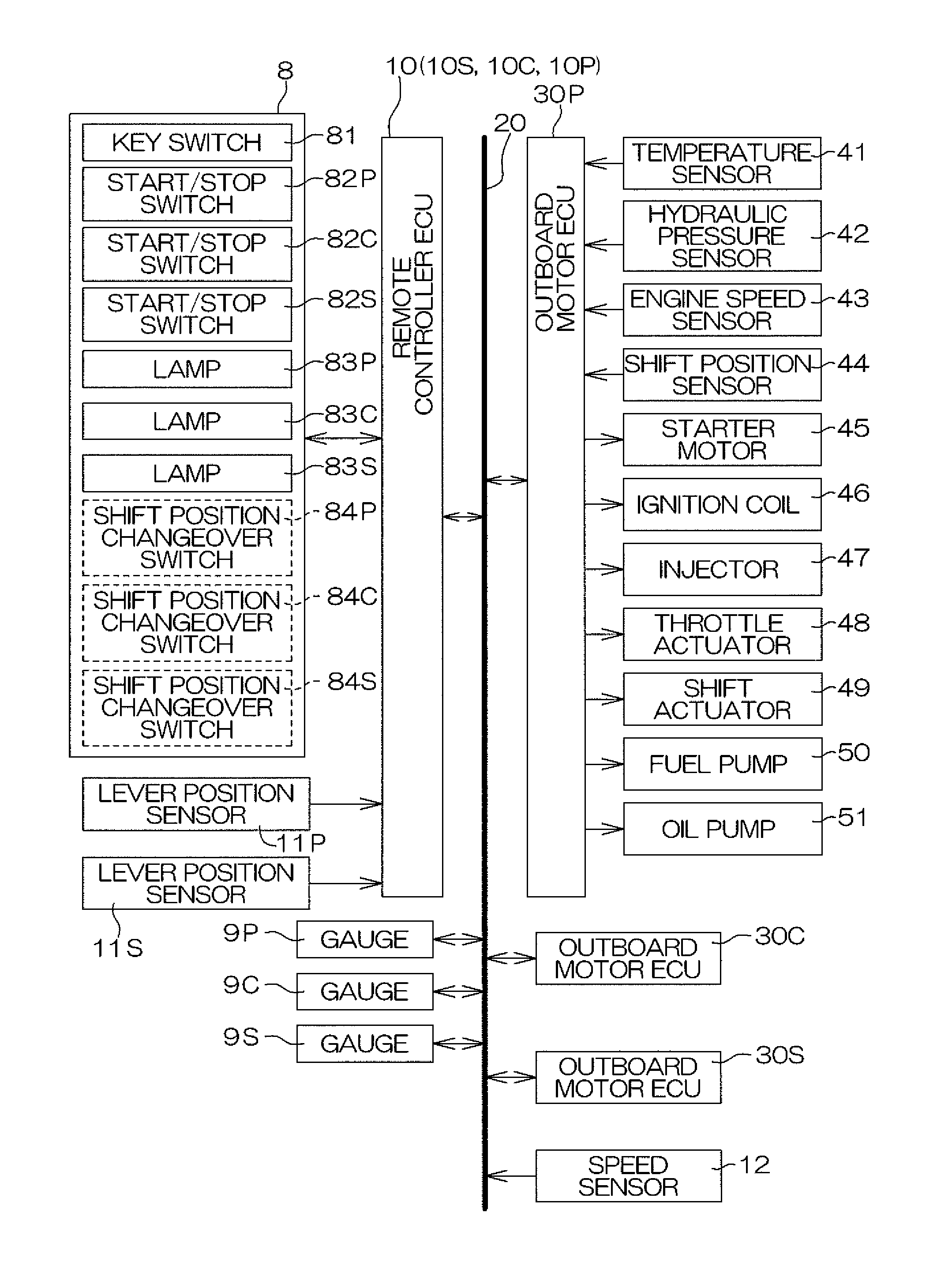
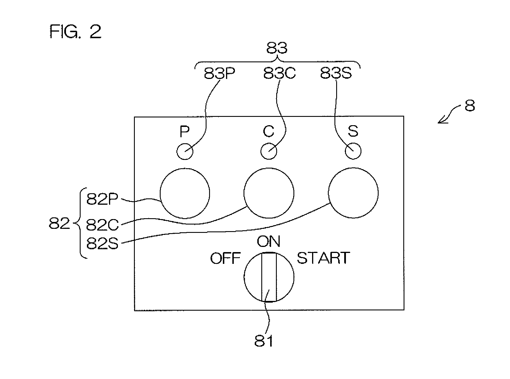
[0072]By this arrangement, the electric power supply of each propulsion devices can be turned on and off individually by operation of the individual electric power supply switch. In this case, the individual electric power supply switch is provided dedicatedly for turning on and off the electric power supply of the propulsion device individually, and operation thereof can be made simple.

Problems solved by technology

However, a problem may occur in a marine vessel adopting a system with which shift control of the plurality of propulsion devices installed on the hull is performed by fewer remote controllers than a total number of the propulsion devices.
Here, an individual electric power supply switch is not provided, and thus the electric power supply of just the faulty central propulsion device 3C cannot be turned off.

Method used


Image

  • Marine vessel propulsion system and marine vessel
  • Marine vessel propulsion system and marine vessel
  • Marine vessel propulsion system and marine vessel

Examples


Embodiment Construction

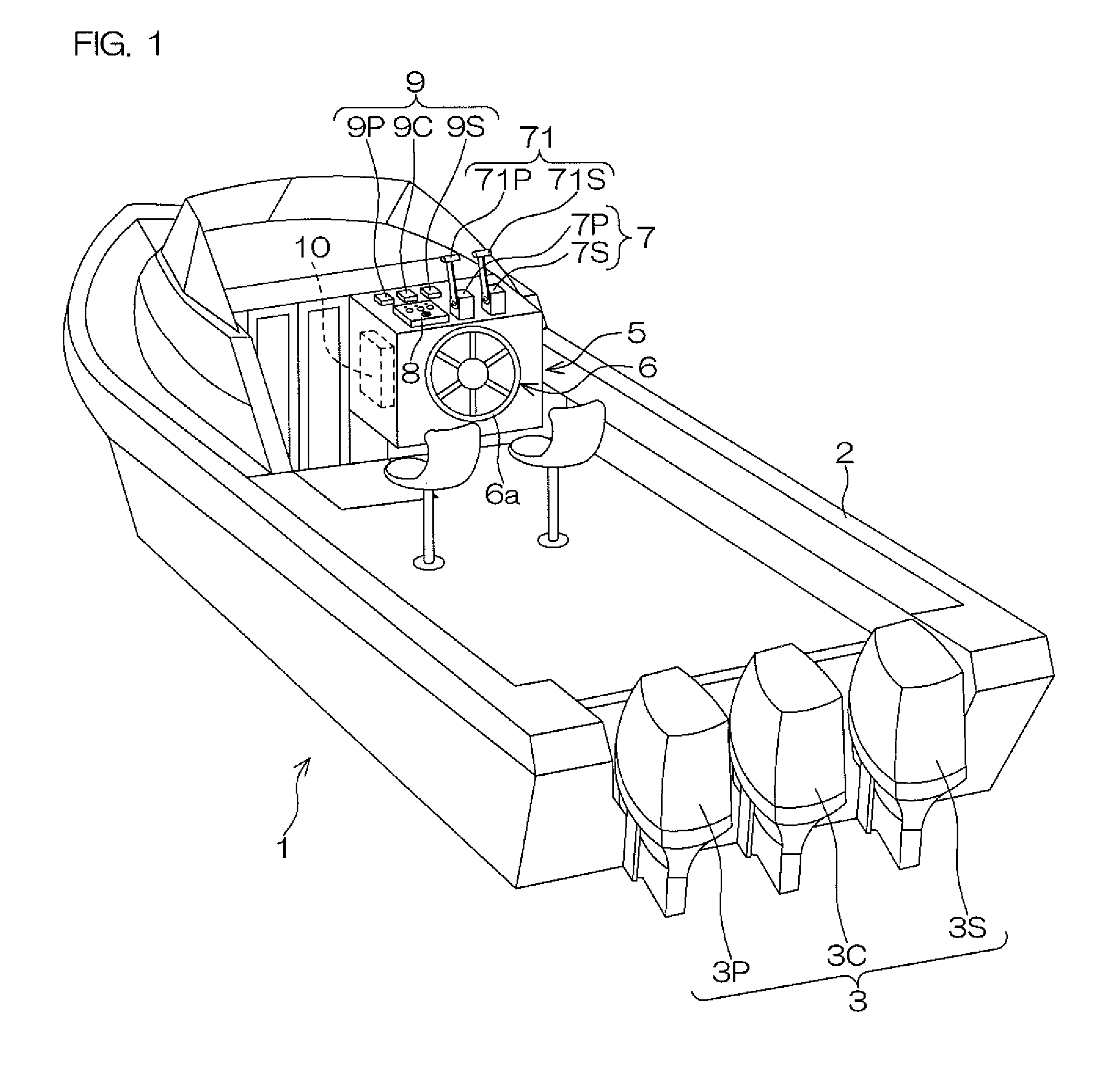
[0101]FIG. 1 is a perspective view for explaining an arrangement of a marine vessel according to a preferred embodiment of the present invention. The marine vessel 1 includes a hull 2 and outboard motors 3 as propulsion devices. A plurality (for example, three, in the preferred embodiment) of the outboard motors 3 are included. The outboard motors 3 are attached in alignment along a stern of the hull 2. When the three outboard motors are to be distinguished, that disposed at a starboard-side shall be referred to as the “starboard-side outboard motor 3S,” that disposed at a center shall be referred to as the “central outboard motor 3C,” and that disposed at a port-side shall be referred to as the “port-side outboard motor 3P.” Each of the outboard motors 3 includes an engine (internal combustion engine) and a propeller (screw) and generates a propulsive force by the propeller being rotated by a driving force of the engine.

[0102]A marine vessel maneuvering compartment 5 is provided at...


PUM


Abstract

A marine vessel propulsion system includes a plurality of propulsion devices, each including a motor and a propeller rotated by the motor. The system further includes a common electric power supply switch arranged to be operated by an operator to turn on and off electric power supplies of the plurality of propulsion devices all at once, an electric power supply control unit arranged to put the electric power supplies of the respective propulsion devices in an on state all at once when the common electric power supply switch is turned on and to put the electric power supplies of the respective propulsion devices in an off state all at once when the common electric power supply switch is turned off, an abnormal state detection unit arranged to detect an abnormal state of each propulsion device, and a power transmission cutoff unit, which is arranged to, when an abnormal state of any of the propulsion devices is detected by the abnormal state detection unit, cut off transmission of power between the motor and the propeller of the propulsion device for which the abnormal state is detected.

Description

BACKGROUND OF THE INVENTION[0001]1. Field of the Invention[0002]The present invention relates to a marine vessel propulsion system and a marine vessel that includes a plurality of propulsion devices.[0003]2. Description of the Related Art[0004]An exemplary propulsion device for a marine vessel is an outboard motor. The outboard motor is, for example, attached to a stern of a hull. The outboard motor is an apparatus that obtains a propulsive force by rotation of a propeller by a power of a motor, such as an engine. A plurality of outboard motors may be attached to the hull in accordance with the required propulsive force. The outboard motor includes an outboard motor ECU (electronic control unit) for motor output control, etc.[0005]A steering operation apparatus, a remote controller for adjusting the output of the outboard motor, and a gauge (meter) for displaying a state of the outboard motor are disposed at a marine vessel maneuvering compartment of the marine vessel. The steering ...

Claims


Application Information

Patent Timeline
IPC IPC(8): B63H21/21
CPCB63H21/22B63H25/42B63H2020/003B63H2021/216
Inventor ITO, MAKOTOBAMBA, TAKAAKIICHIKAWA, NORIYOSHIIKEGAYA, YUKIAKUZAWA, SHU
Owner YAMAHA MOTOR CO LTD
Learn More