Image Forming Apparatus And Foam Application Device

a technology of foam application and forming apparatus, which is applied in the direction of coatings, printing, other printing apparatus, etc., can solve the problems of blurring the color on the boundary, taking time to dry the droplets after, etc., and achieves the effect of easy control of supply amount, and maintaining the quality of foam

Inactive Publication Date: 2010-09-30
RICOH KK
View PDF23 Cites 10 Cited by
  • Summary
  • Abstract
  • Description
  • Claims
  • Application Information

AI Technical Summary

Benefits of technology

[0027]In an image forming apparatus and a foam application device according to an embodiment of the present invention, a discharge opening is formed on the supplying unit supplying the foam through the supply opening to the application unit applying foam to the target application member; and the amount of foam introduced into the supplying unit is greater than the amount of foam supplied to the application unit. By having these features, it may become possible to uniformly apply a fluid, a gel, or a fluid and a gel so as to form a film having a substantially even thickness, control the supply amount easily, and maintain the quality of the foam to be applied at a certain level.
[0028]Further, an image forming apparatus and a foam application device according to an embodiment of the present invention include the application unit applying the foam; the channel collecting extra foam remaining without having been applied; and the heat unit heating the extra foam on the channel to return the extra foam to a liquid form. By having these features, it may become possible to uniformly apply a fluid, a gel, or a fluid and a gel so as to form a film having a substantially even thickness, collect the extra foam, and waste the collected extra foam when necessary to maintain the quality of the foam to be applied at a certain level.

Problems solved by technology

Because of this feature, such image forming apparatus may have a drawback causing problems such as the feathering in which dots formed by droplets have an irregular (beard) shape, and color bleeding in which when ink droplets having different colors are applied adjacent to each other on a sheet, the ink droplets having different colors are mixed on the boundary between the droplets, thereby blurring the color on the boundary.
In addition, there is another problem that it takes time to dry the droplets after being applied to the sheet.

Method used


Image

  • Image Forming Apparatus And Foam Application Device
  • Image Forming Apparatus And Foam Application Device
  • Image Forming Apparatus And Foam Application Device

Examples


first embodiment

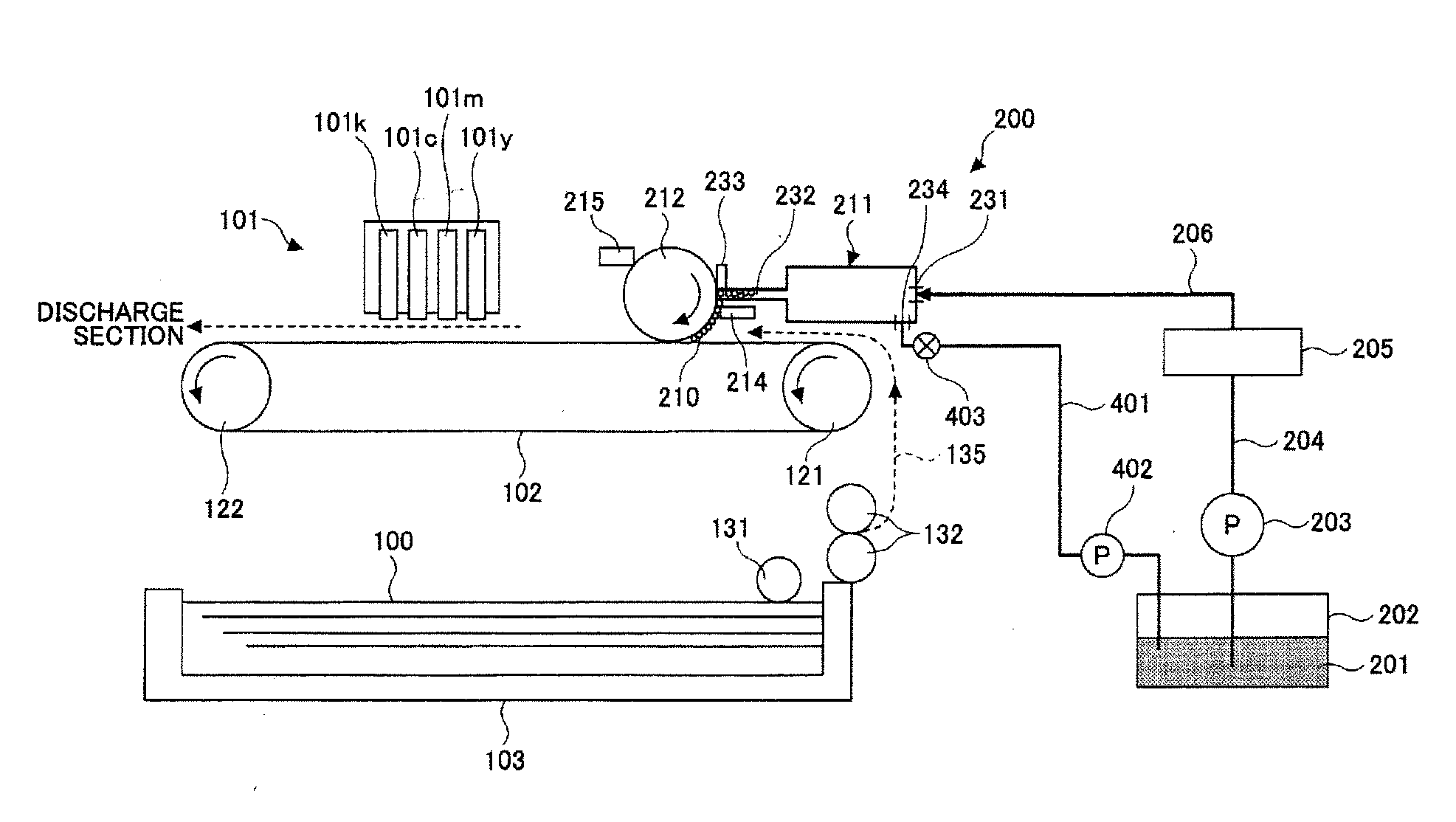
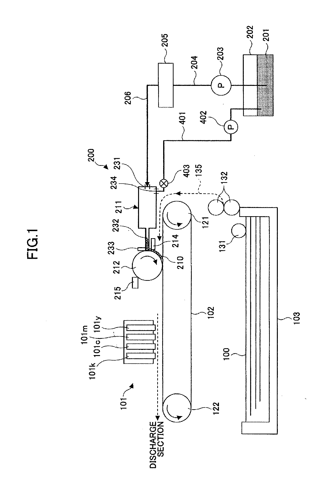
[0071]In the following, embodiments of the present invention are described with reference to the accompanying drawings. First, an example of an image forming apparatus having a foam application device according to the present invention is described with reference to FIG. 1. FIG. 1 is a schematic diagram showing an exemplary configuration of the image forming apparatus. As shown in FIG. 1, the image forming apparatus includes a recording head unit 101, a feeding belt 102, a sheet feed tray 103, and a foam application device 200 (a device for applying foam bubbles to an application target member) according to an embodiment of the present invention. The recording head unit 101 serves as an image forming unit by ejecting droplets onto a sheet 100 as a recording medium to be recorded to form an image on the sheet 100. The sheets 100 are stacked in the sheet feed tray 103. The feeding belt 102 feeds the sheet 100. The foam application device 200 is provided on the upstream side of the rec...

second embodiment

[0104]Next, another example of an image forming apparatus having a foam application device according to the present invention is described with reference to FIG. 10. FIG. 10 is a schematic diagram showing an exemplary configuration of the reservoir section in the foam application device. As shown in FIG. 10, the reservoir section 211 includes a foam reservoir container 700 having a cylindrical shape. The introduction opening 231 is formed on one end side in the axis direction of the foam reservoir container 700. The discharge opening 234 is formed on the other end side in the axis direction of the foam reservoir container 700. Further, in the foam reservoir container 700, a feeding agitation member 701 having a screw shape is disposed along the axis direction of the foam reservoir container 700, so that the foam bubbles 210 can swiftly and uniformly spread around the supply opening 232 as the feeding agitation member 701 rotates. By having this structure, it becomes possible to feed...

third embodiment

[0106]Next, still another example of an image forming apparatus having a foam application device according to the present invention is described with reference to FIG. 11. FIG. 11 is a schematic plan view showing an exemplary configuration of the reservoir section in the foam application device. As shown in FIG. 11, a channel 711 provides communication between the introduction opening 231 and the discharge opening 234, and the width of the channel 711 becomes narrower as the foam approaches the discharge opening 234. The supply opening 232 is formed along the direction from the introduction opening 231 to the discharge opening 234 (parallel to the axis direction of the application roller 212). By having this structure, a supply pressure of the foam bubbles 210 becomes constant along the longitudinal direction of the supply opening 232 and a time period required to fill the entire reservoir section 211 with the foam bubbles 210 may be reduced because the width of the channel 711 is g...


PUM


Abstract

A disclosed image forming apparatus is capable of solving the problems of deterioration of a foam application function and driving systems caused by the dried and fixed foam remaining without being applied. The image forming apparatus includes a foam forming section forming foam, a reservoir section supplying foam formed by the foam forming section to an application roller, a discharge channel through which extra foam is collected from the reservoir section, and a heating unit for heating the extra foam to return the extra foam to a liquid form. The discharged liquid prepared by defoaming the foam discharged through the discharge channel is returned to a container containing the defoamed liquid.

Description

TECHNICAL FIELD[0001]The present invention relates to an image forming apparatus and a foam application device.BACKGROUND ART[0002]Conventionally, an inkjet recording device has been known as an image forming apparatus such as a printer, a facsimile machine, a copier, and a multifunctional peripheral having those functions, the image forming apparatus employing the liquid-ejection recording method in which, for example, a recording head ejecting ink droplets is used. The image forming apparatus employing the liquid-ejection recording method is capable of ejecting droplets from its recording head onto a fed sheet (or an OHP sheet or any medium on which ink droplets or other liquid can be applied, and may be referred to as a recording medium, a recording paper, a recording sheet, or the like) to form (the terms “form”, “record”, “type”, “image”, and “print” may be regarded as synonymous with each other) an image on the fed sheet. The image forming apparatuses employing the liquid-ejec...

Claims


Application Information

Patent Timeline
Patent Type & Authority Applications(United States)
IPC IPC(8): B41J2/015B05C11/02
CPCB41J11/0015
Inventor IMOTO, SHINJIMATSUMOTO, KAZUYOSHIICHIMURA, MINORIIZUMIKAWA, MANABUKATO, YASUHISAKATANO, YASUOHOSHINO, SEIJITSUDA, MASAAKI
Owner RICOH KK
Why Eureka
Try Eureka