
B1 mapping in MRI system using k-space spatial frequency domain filtering

a spatial frequency domain and mapping technology, applied in the field of generating multidimensional maps of the spatial distribution of radio frequency magnetic fields, can solve the problems of introducing unwanted effects of rf fields, inability to achieve absolutely uniform homogeneity, and inability to achieve absolute linear gradients, etc., to achieve a higher resolution b1 map

Active Publication Date: 2010-09-23
TOSHIBA MEDICAL SYST CORP
View PDF7 Cites 44 Cited by
  • Summary
  • Abstract
  • Description
  • Claims
  • Application Information

AI Technical Summary

Benefits of technology

[0064]The current application describes a method for determining or calculating B1 maps, from experimentally acquired MR data of a suitable kind. In particular, advantages can be realized in accuracy or practical performance or speed when generating B1 maps, especially inside humans or moving, living subjects.
[0094]The exemplary processes allow higher resolution, in terms of tag lines being potentially closer together, than in image-domain-based analysis of the tag lines. Note that the filtering step, or the step of generating an envelope of the modulation part, will generally introduce a blurring or loss of resolution in the B1 map, which is on the order of the spacing of the tag lines. Thus, closer tag line spacing, such as two, three or four pixels per cycle, as opposed to, say, 5-10 pixels per cycle, can yield a higher resolution B1 map.

Problems solved by technology

Unfortunately, the ideals of absolutely uniform homogeneity, absolutely linear gradients, etc., desired for various magnetic / RF fields in the MRI system are not realized in practice.
Spatial inhomogeneities of the RF fields introduce unwanted effects, including various artifacts in images, degradations in image contrast, or degradation or failure of various quantification methods.
When considering prior art use of SPAMM to achieve B1 mapping, it appears that there is limited published material.
The inventors consider this to be not a particularly effective method.
Many of such prior techniques for B1 mapping have limitations of acquisition speed.
Motion artifacts in the body can degrade individual images, but more importantly, they can cause inconsistencies between pairs of images.
Inaccuracies and biases can arise.
This can limit scan time or limit temporal resolution, or introduce errors in the presence of attempted faster acquisitions.
Intrinsic SNR can adversely affect accuracy, resolution or scan acquisition time.
The associated acquisition technique for reading out the image may have limitations or artifacts, which would propagate into the associated maps.
For example, EPI, as used in Jiru, 2006, can have significant geometric distortion, or chemical shift, or utilizes fat suppression, making it impractical to determine the B1 within fat.
Most of the prior techniques require longer acquisitions, costing several minutes of scanning for 2-D or 3-D maps.
This becomes a source of error in the resulting B1 determination, or else requires additional acquisitions to simultaneously determine both B1 and the other factors.
When scans are longer, or more than one scan must be combined, physiological motion can degrade the individual acquired images, or make the separate images become inconsistent, ruining the ratios.
Motion artifact can make techniques useless in human torsos.
Detection of local signal variations in a tagged image, when the unmodulated image itself contains significant local variation, is not easy, especially when working in the image domain.
If the SPAMM acquisition is used with image-domain peak-and trough detection method, significant error can arise if a neighboring peak and trough are used together in a ratio, but they have other confounding effects, like major differences in ρ.

Method used


Image

  • B1 mapping in MRI system using k-space spatial frequency domain filtering
  • B1 mapping in MRI system using k-space spatial frequency domain filtering
  • B1 mapping in MRI system using k-space spatial frequency domain filtering

Examples


Embodiment Construction

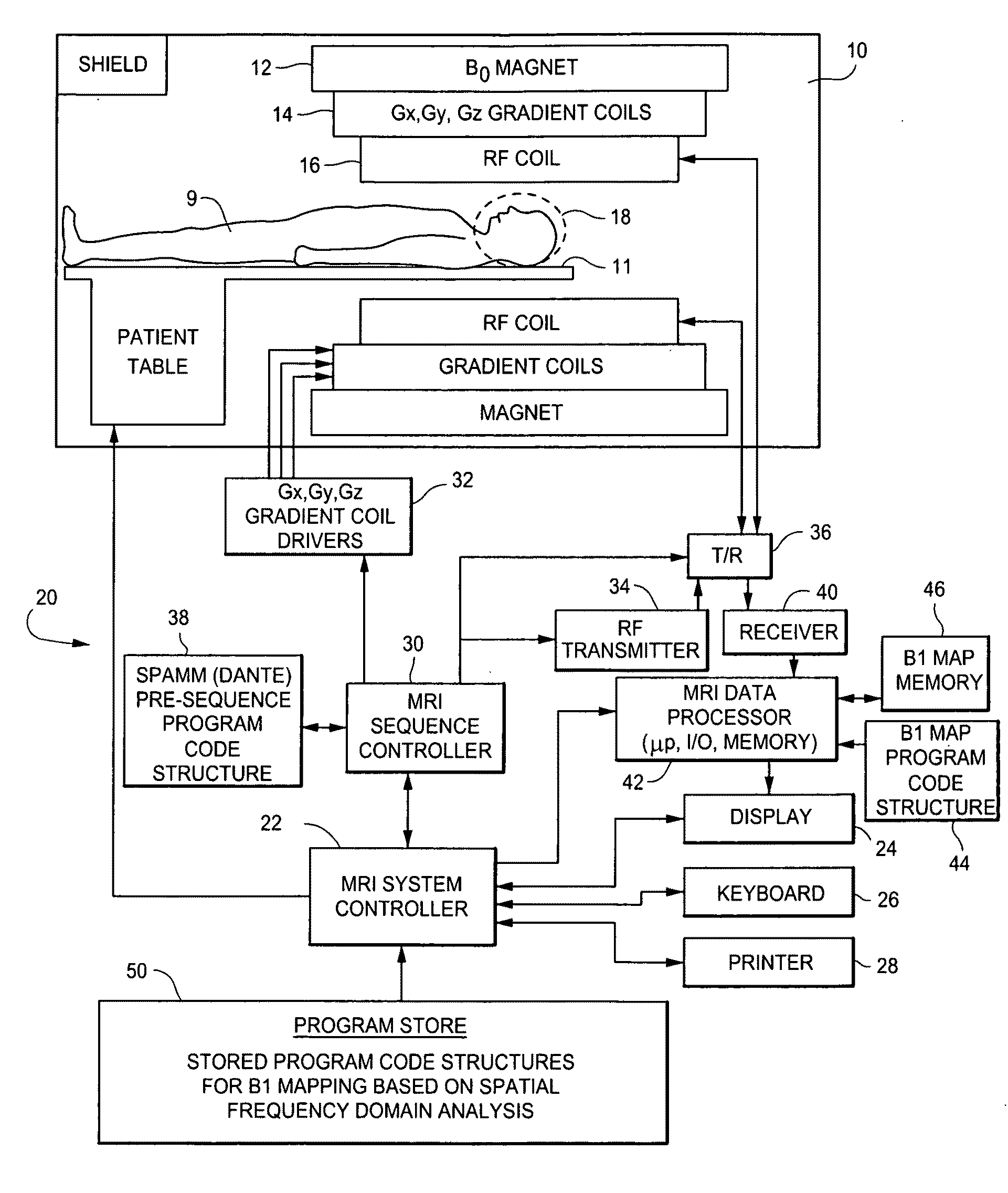
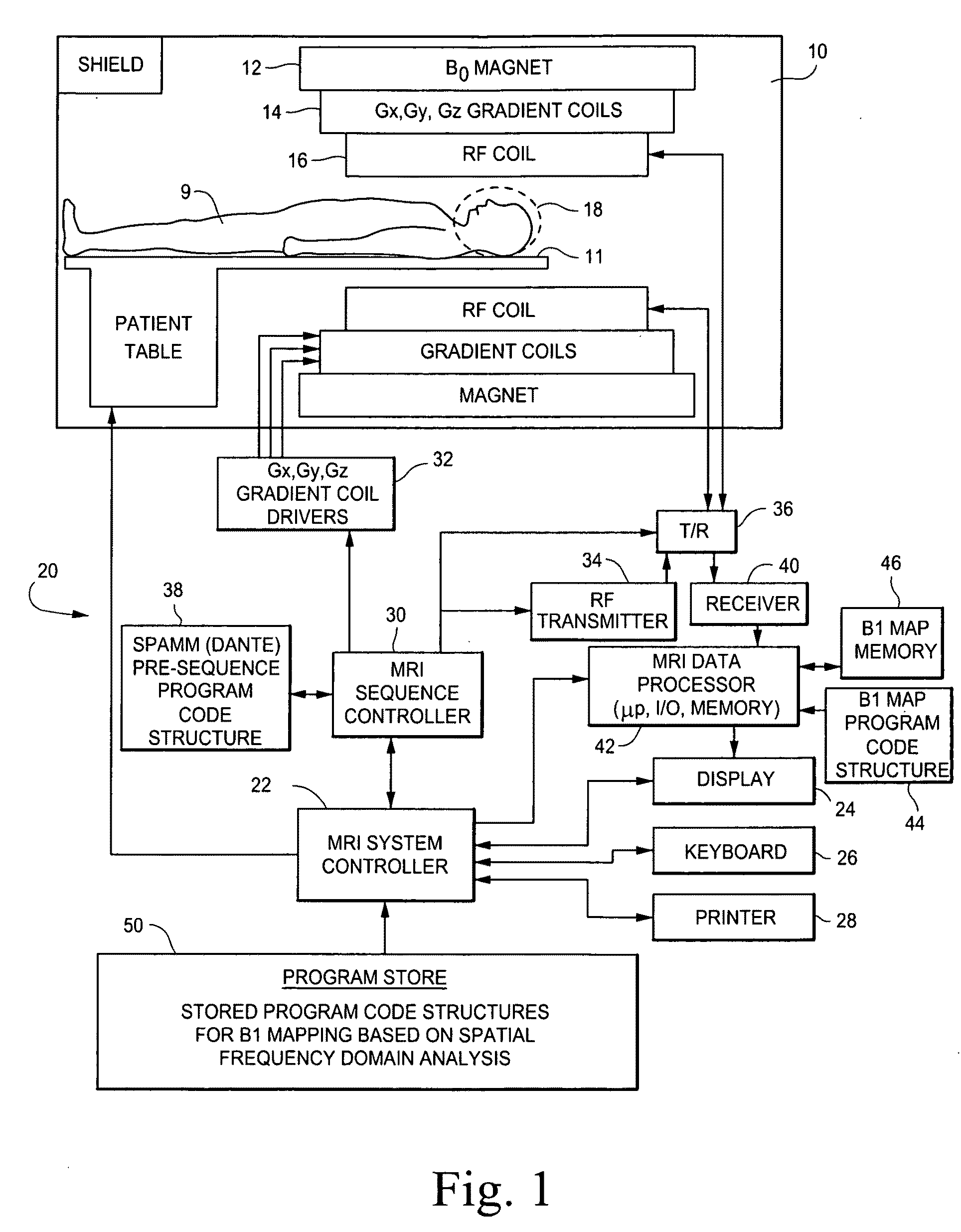
[0106]The MRI system shown in FIG. 1 includes a gantry 10 (shown in schematic cross-section) and various related system components 20 interfaced therewith. At least the gantry 10 is typically located in a shielded room. One MRI system geometry depicted in FIG. 1 includes a substantially coaxial cylindrical arrangement of the static field B0 magnet 12, a Gx, Gy and Gz gradient coil set 14 and an RF coil assembly 16. Along the horizontal axis of this cylindrical array of elements is an imaging volume 18 shown as substantially encompassing the head of a patient 9 supported by a patient table 11.

[0107]An MRI system controller 22 has input / output ports connected to display 24, keyboard 26 and printer 28. As will be appreciated, the display 24 may be of the touch-screen variety so that it provides control inputs as well.

[0108]The MRI system controller 22 interfaces with MRI sequence controller 30 which, in turn, controls the Gx, Gy and Gz gradient coil drivers 32, as well as the RF transm...


PUM


Abstract

Frequency filtering of spatially modulated or “tagged” MRI data in the spatial frequency k-space domain with subsequent 2DFT to the spatial domain and pixel-by-pixel arithmetic calculations provide robust ratio values that can be subjected to inverse trigonometric functions to derive B1 maps for an MRI system.

Description

BACKGROUND[0001]1. Technical Field[0002]This application describes methods and apparatus for generating multi-dimensional maps of the spatial distribution of radio frequency (RF) magnetic fields (typically labelled as the “B1” field) in MRI (magnetic resonance imaging) systems.[0003]2. Related Art[0004]Magnetic resonance imaging (MRI) systems are by now well known and many different types of commercially available MRI systems are regularly employed for medical research and / or diagnostic purposes. Although there are many variations in detailed image acquisition processes and / or MRI system geometries, they all share some basic fundamental principles.[0005]For example, MRI systems all utilize the principle of nuclear magnetic resonance (NMR) wherein nuclei having a net magnetic moment (e.g., nuclei having an odd number of protons such as the hydrogen nucleus) are immersed in a static background magnetic field B0. Ideally, this background static magnetic field is homogeneous throughout ...

Claims


Application Information

Patent Timeline
Patent Type & Authority Applications(United States)
IPC IPC(8): G06K9/00G01R33/54
CPCG01R33/246G06T11/003G01R33/56333G01R33/443
Inventor DANNELS, WAYNE R.WHEATON, ANDREW J.
Owner TOSHIBA MEDICAL SYST CORP
Learn More