
Sensing Apparatus and Method for Detecting a Three-Dimensional Physical Shape of a Body

a three-dimensional physical shape and sensing device technology, applied in the direction of instruments, measurement devices, instruments, etc., can solve the problems of not being able to operate by trained specialists or technicians, and not being able to use in shoe stores, and achieve the effect of simple design

Active Publication Date: 2010-09-23
CORPUS E
View PDF14 Cites 75 Cited by
  • Summary
  • Abstract
  • Description
  • Claims
  • Application Information

AI Technical Summary

Benefits of technology

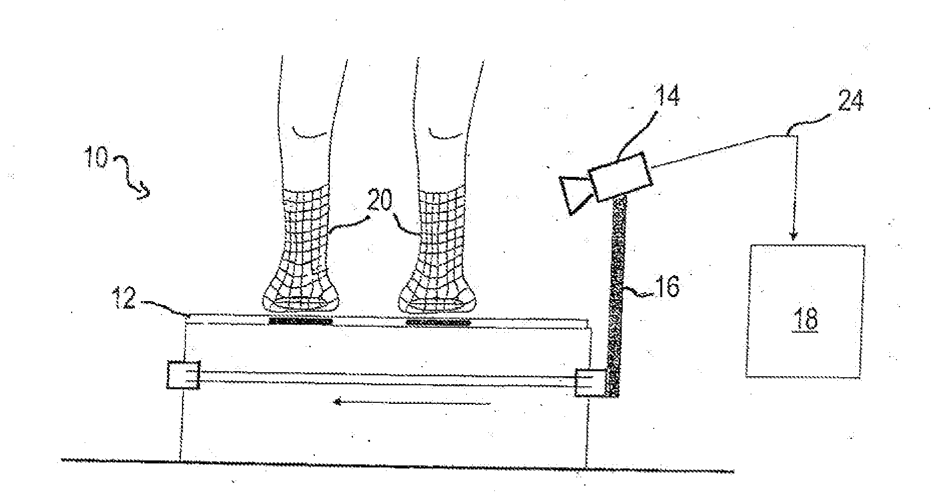
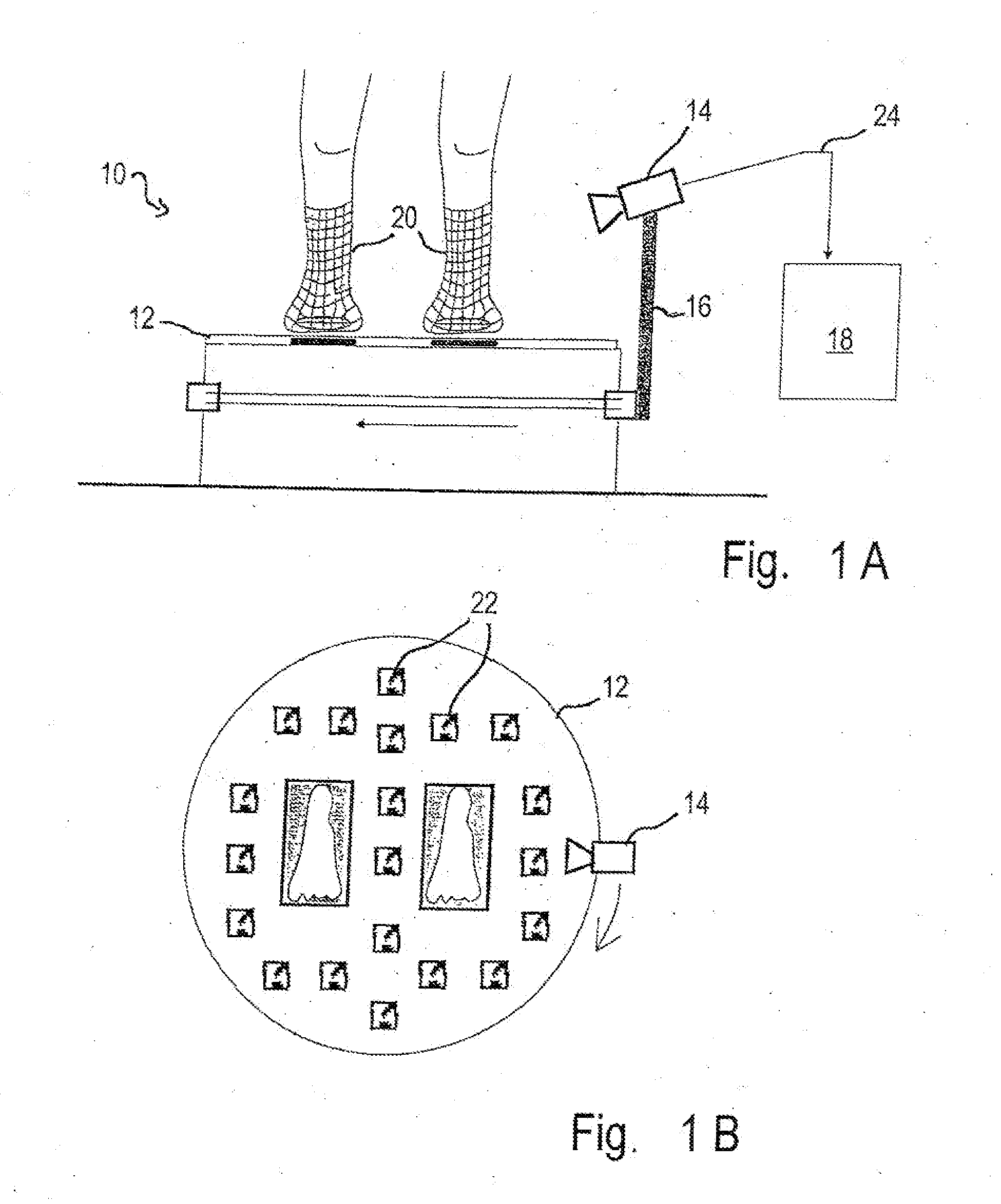
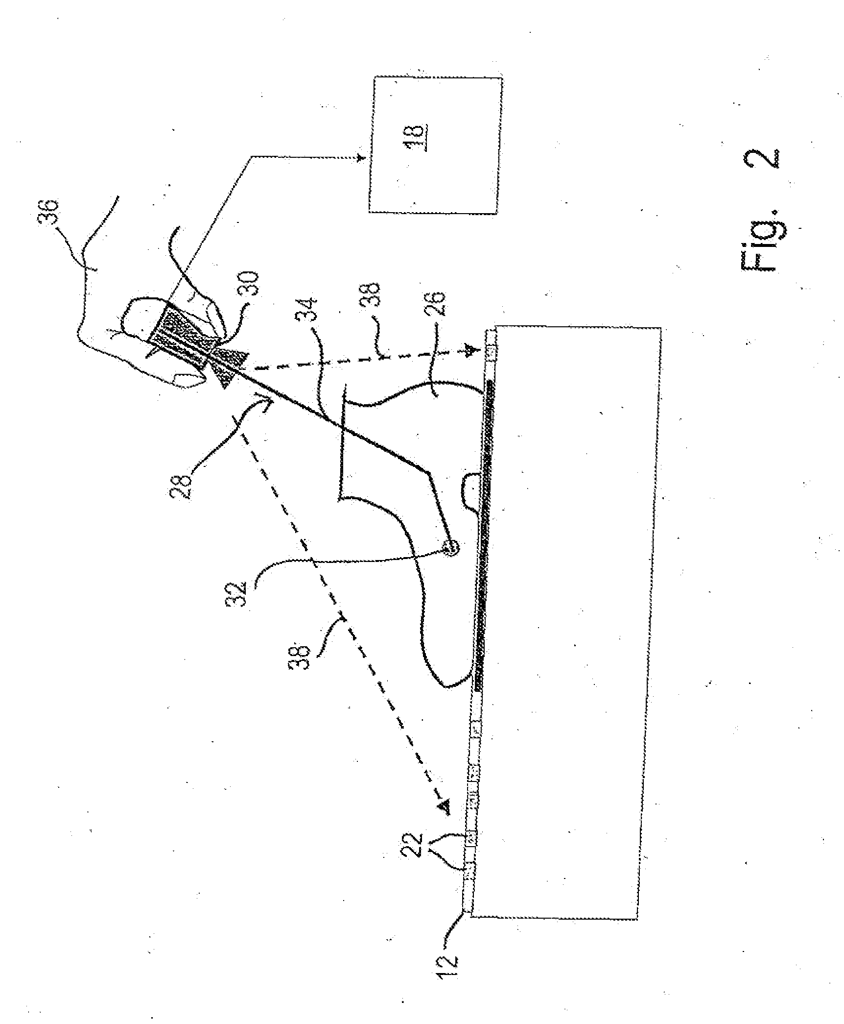
[0014]The sensing device allows an, e.g., tactile scanning of, more particularly, interiors of bodies and, in doing so, allows the respective spatial positions of the sensing end to be established by way of the photogrammetric image recordings of a camera that is mechanically rigidly connected with the sensing end, purely from a photogrammetrically marked base plate, i.e. the surface provided with marks suitable to be automatically photogrammetrically evaluated and on which the body is fixed in place. Any measuring mechanisms requiring time-consuming calibration are thus made dispensable. The only measuring aid, which contains absolutely precise and known distances, is the photogrammetrically marked base plate; it can be produced in a simple manner in terms of printing technology and with high absolute precision. This makes the sensing device according to the invention and the method according to the invention self-calibrating, allowing them to be employed using simple cameras and imaging optics.
[0017]The present invention further provides a method according to claim 12. In a preferred embodiment, the interior of a hollow body, in particular of a shoe, is detected, the camera remaining outside of the hollow body while the interior is scanned. The convex envelope of the interior is determined from an overall generated point cloud of coordinates of the interior from established positions. A comparison of the established positions of the sensing end with the convex envelope of the interior allows those points of established positions to be recognized which do not lie on the convex envelope. These points are deleted. Any errors in measurement that arise, e.g., in that the person guiding the sensing arrangement moves away from the inner wall, are thus corrected automatically by removing the incorrect measuring points. This allows the sensing arrangement to be configured particularly simply since it need not have a release contact which releases an image recording or marks an image recorded by the camera only when the sensing end is in tactile contact with the inner wall of the footwear. Rather, the moving camera records images continuously, for example, and does not require synchronization to the sensing end or to the movement.
[0019]In addition to embodiments which provide for the sensing arrangement to be guided manually, the invention also comprises motor guides for moving the sensing end within the interior in a predefined or random movement such that numerous points on the inner wall are touched, while the camera makes recordings of the photogrammetrically marked surface at the same time. Owing to the property of self-calibration being maintained, the motor drive may be of a very simple design.
[0021]Preferably, the positioning of the sensing end during this spherical movement is facilitated by a trough-shaped seat for receiving the sensing end in the base plate.

Problems solved by technology

These systems are very involved in respect of calibration, space requirements and the very expensive photogrammetric cameras, and are therefore not suitable for use in a shoe store.
They can only be operated by trained specialists or technicians, in particular also because of the calibration procedures to be repeated many times before the actual digitization starts.

Method used


Image

  • Sensing Apparatus and Method for Detecting a Three-Dimensional Physical Shape of a Body
  • Sensing Apparatus and Method for Detecting a Three-Dimensional Physical Shape of a Body
  • Sensing Apparatus and Method for Detecting a Three-Dimensional Physical Shape of a Body

Examples


first embodiment

[0031]In a first embodiment, the sensing end 32 mainly contacts the inner wall of the footwear 26 to scan it mechanically; here, the sensing end 32 may be fitted with a mechanical and / or optical and / or inductive and / or acoustical contact mechanism which upon contact with the inner wall generates a contact signal. Either an image is not recorded until triggered by the contact signal, or, preferably, the camera 30 records images continuously in a video mode and, based on the contact signal, those images are selected which were recorded at the moments the contact signals were supplied.

[0032]In a second embodiment, the sensing end 32 disposes of a mechanically linearly resiliently displaceable sensing tip having a linear displacement sensor. Upon contact of the sensing tip with the inner wall of the shoe 26, a displacement signal is transferred from the linear displacement sensor to the computing unit 18. A correction vector is calculated from the displacement signal and is added in the...

third embodiment

[0033]In a third embodiment, the sensing end 32 disposes of an opto-electronic and / or acoustic distance measuring device for measuring a distance of the sensing end 32 from the spatial shape in at least one defined direction. The measured distance is transferred to the computing unit 18 and a correction vector is calculated from the measured distance. This correction vector is added to the space coordinates of the sensing end 32 photogrammetrically established from the images recorded by the camera 30. In this way, the coordinates of the inner wall are established without the sensing end 32 mechanically contacting the inner wall.

[0034]In all of the embodiments, the camera 30 preferably permanently records images of the photogrammetrically marked base plate 12 during the scanning of the inner wall and transfers these images to the computing unit 18, which uses these image sequences to calculate, applying the methods of photogrammetry known to those skilled in the art, the respective ...


PUM


Abstract

A sensing device having a sensing arrangement with a sensing end (32) for coming into contact with a surface to be scanned of a body (26), a camera (30), and a connecting device (34) for rigidly connecting the camera with the sensing end, the camera being arranged such that it can detect a surface (12) which is provided with marks suitable to be automatically photogrammetrically evaluated and on which the body to be scanned has been placed, when the sensing end comes into contact with different points of the surface to be scanned of the body. The sensing device further has a photogrammetric evaluation program for a computing unit (18), the computing unit being configured such that image signals generated by the camera can be routed to the computing unit and the evaluation program can calculate the 3D coordinates of the surface to be scanned from the sequence of recorded and transmitted image sections using the marks (22) suitable to be automatically photogrammetrically evaluated. A method of detecting a three-dimensional spatial shape of a body, in particular the spatial shape of an interior of a hollow body, the method including the following steps: fastening the body to be digitized on a surface (12) which, at known positions, is provided with marks (22) suitable to be automatically photogrammetrically evaluated, and providing the sensing device. Further steps are the scanning of a point on the spatial shape to be detected by means of the sensing end (32) of the sensing arrangement (28), recording at least one section of the photogrammetrically marked surface by the camera (30) while the sensing end scans the point, a plurality of marks suitable to be photogrammetrically evaluated being detected, and repeating the steps of scanning and recording for a multitude of different points of the spatial shape to be detected. The recorded images are evaluated by an evaluation program.

Description

FIELD OF THE INVENTION[0001]The present invention relates to a sensing device and a method of detecting a three-dimensional spatial shape of a body, including a sensing end for scanning a surface to be scanned of the body, and a camera, a multitude of points on the surface to be scanned being scanned using the sensing end.[0002]The manufacture of well fitting shoes within the scope of the so-called mass customization usually requires the 3D digitization of the spatial shape of the feet of the customer. This data is used for selecting from a collection of shoe lasts that are available physically or virtually as a 3D data set, that shoe last with which the best fitting shoe can be produced (mass customization of a best fitting shoe). In the more demanding, individual mass customization business model, an individual shoe last is fabricated from the 3D data set of the digitized foot and an individual custom-made shoe is produced hereby.[0003]It is, to date, still very difficult to estab...

Claims


Application Information

Patent Timeline
Patent Type & Authority Applications(United States)
IPC IPC(8): H04N13/02
CPCA43D1/06G01B11/24G01B5/20
Inventor PFEIFFER, RENERUTSCHMANN, DIRK
Owner CORPUS E
Learn More