Piezoelectric Actuator, Method Of Manufacturing Piezoelectric Actuator, Liquid Ejection Head, Method Of Manufacturing Liquid Ejection Head And Image Forming Apparatus

Active Publication Date: 2010-09-23
FUJIFILM CORP
View PDF4 Cites 13 Cited by
  • Summary
  • Abstract
  • Description
  • Claims
  • Application Information

AI Technical Summary

Benefits of technology

[0008]The present invention has been contrived in view of these circumstances, an object thereof being to provide a piezoelectric actuator having high durability whereby deterioration of the amount of displacement can be suppressed, a method of manufacturing a piezoelectric actuator, a liquid ejection head comprising the piezoelectric actuator, a method of manufacturing a liquid ejection head, and an image forming apparatus.
[0010]According to the first mode described above, by employing a piezoelectric body formed so as to have orientation by a film formation method (for example, a sputtering method), it is possible to prevent the direction of polarization from changing readily even when the piezoelectric body is driven repeatedly. Consequently, it is possible to achieve a piezoelectric actuator having high durability and a stable amount of displacement of the diaphragm, and a liquid ejection head comprising this piezoelectric actuator. Moreover, the piezoelectric body formed so as to have orientation by sputtering has high voltage tolerance and therefore the voltage applied to the piezoelectric actuator is raised (desirably, 3 kV / mm or above, 25 kV / mm or lower) and the amount of displacement of the diaphragm can be increased.
[0016]According to this mode described above, it is possible to raise the durability of the piezoelectric actuator and suppress degradation of the amount of displacement, and a liquid ejection head having high durability and a stable liquid ejection amount can be created.
[0019]According to this mode, the piezoelectric layer is not constricted by the diaphragm and therefore the amount of displacement of the piezoelectric layer can be increased further.
[0025]According to this mode described above, it is possible to apply a high voltage compared to a piezoelectric ceramics formed by a calcination method, and therefore the amount of displacement of the piezoelectric element can be increased. By this means, it is possible to achieve high density in a liquid ejection head.
[0033]According to the present invention, by employing a piezoelectric body formed so as to have orientation by a film formation method (for example, a sputtering method), it is possible to prevent the direction of polarization from changing readily even when the piezoelectric body is driven repeatedly. Consequently, it is possible to achieve a piezoelectric actuator having high durability and a stable amount of displacement of the diaphragm, and a liquid ejection head comprising this piezoelectric actuator. Moreover, the piezoelectric body formed so as to have orientation by sputtering has high voltage tolerance and therefore the voltage applied to the piezoelectric actuator is raised (for example, 3 kV / mm or higher, 25 kV / mm or lower) and the amount of displacement of the diaphragm can be increased.

Problems solved by technology

Therefore, if a piezoelectric ceramics layer is used as the piezoelectric layer, there is a possibility that the direction of polarization changes readily and the amount of displacement deteriorates.
Consequently, in a piezoelectric layer formed by calcination of ceramic, it is difficult to obtain a piezoelectric actuator having high reliability.
Moreover, since the piezoelectric ceramics layer formed by calcination of ceramics has lower voltage tolerance, then it is difficult to increase the amount of displacement of the piezoelectric ceramics layer by raising the applied voltage value.

Method used


Image

  • Piezoelectric Actuator, Method Of Manufacturing Piezoelectric Actuator, Liquid Ejection Head, Method Of Manufacturing Liquid Ejection Head And Image Forming Apparatus
  • Piezoelectric Actuator, Method Of Manufacturing Piezoelectric Actuator, Liquid Ejection Head, Method Of Manufacturing Liquid Ejection Head And Image Forming Apparatus
  • Piezoelectric Actuator, Method Of Manufacturing Piezoelectric Actuator, Liquid Ejection Head, Method Of Manufacturing Liquid Ejection Head And Image Forming Apparatus

Examples


Embodiment Construction

[0044]Below, preferred embodiments of a piezoelectric actuator, a method of a manufacturing a piezoelectric actuator, a liquid ejection head comprising the piezoelectric actuator, a method of manufacturing a liquid ejection head and an image forming apparatus according to the present invention will be described with reference to the accompanying drawings.

Composition of Image Forming Apparatus

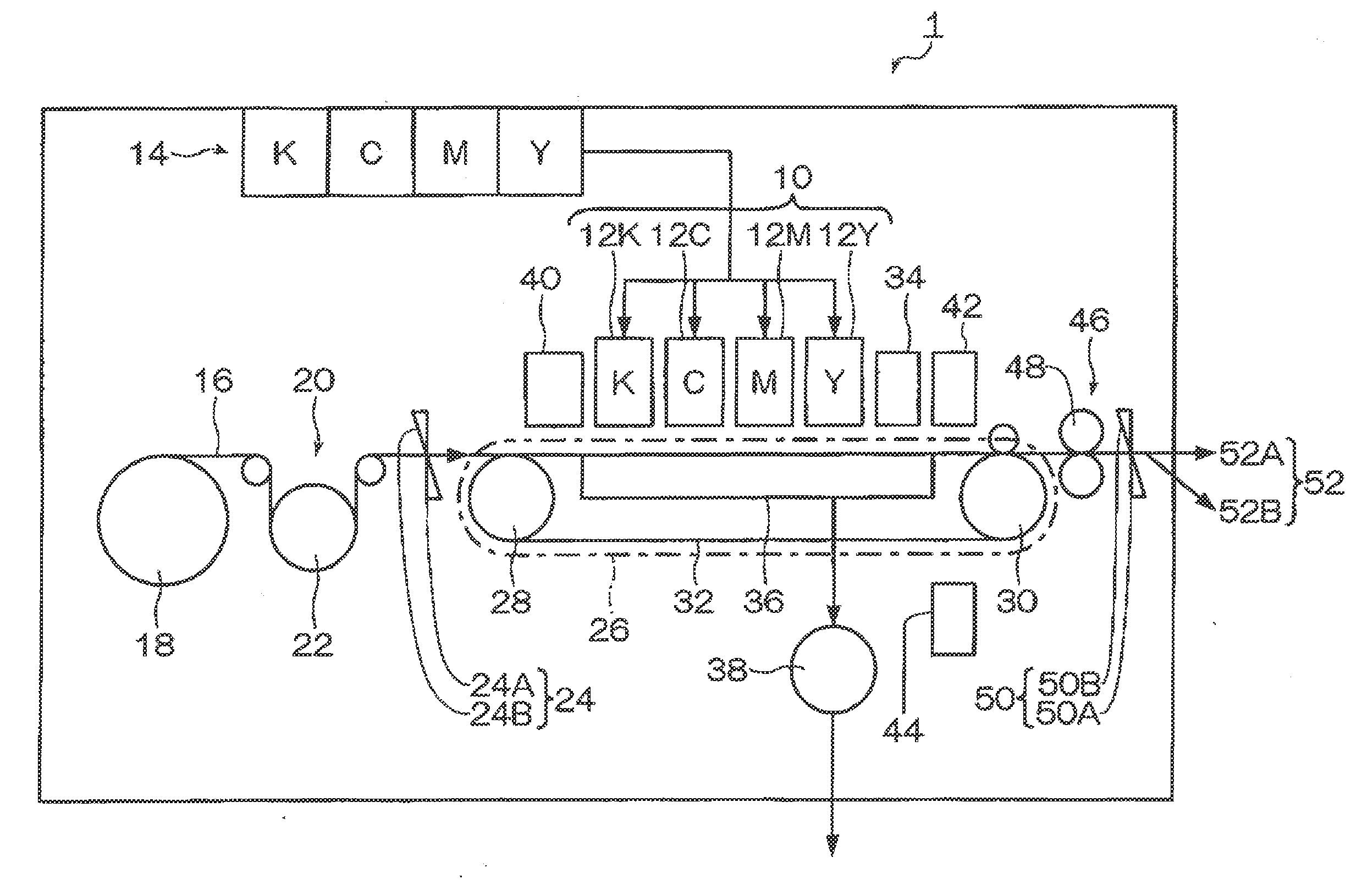
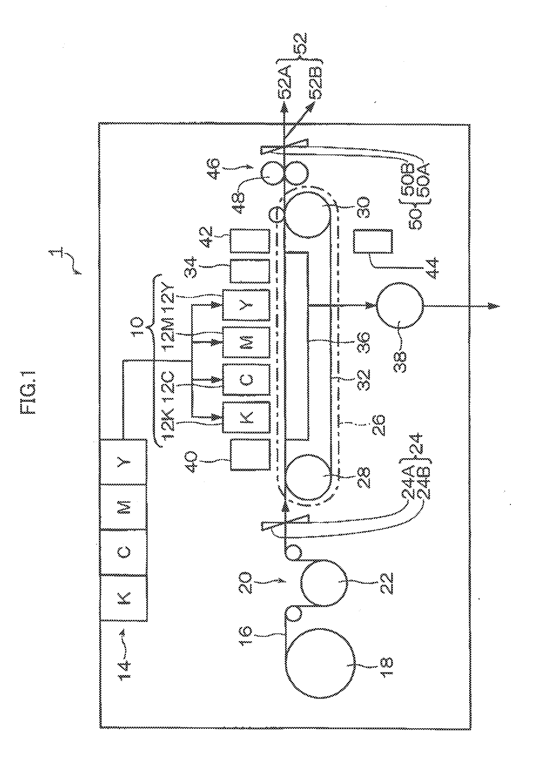
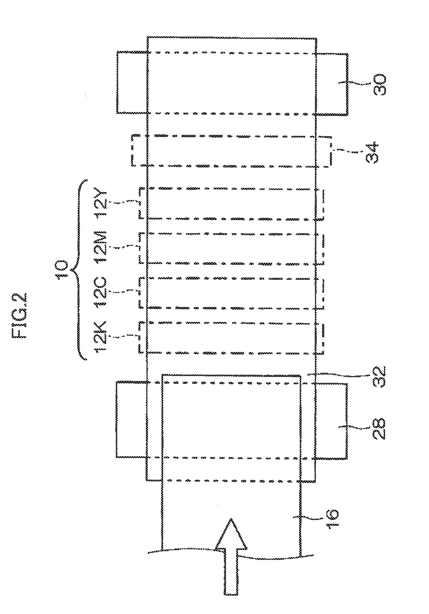
[0045]Firstly, the composition of the liquid ejection head and the image forming apparatus (inkjet recording apparatus) comprising a piezoelectric actuator relating to an embodiment of the present invention will be described. FIG. 1 is a diagram showing a schematic view of an inkjet recording apparatus relating to one embodiment of the present invention, and FIG. 2 is a plan diagram showing the periphery of the print unit of the inkjet recording apparatus.

[0046]As shown in FIG. 1, the inkjet recording apparatus 1 relating to the present embodiment comprises a print unit 10 having liquid ejection...


PUM

PropertyMeasurementUnit
Electric fieldaaaaaaaaaa
Shapeaaaaaaaaaa

Abstract

A piezoelectric actuator includes: a piezoelectric layer formed by a film formation method so as to have orientation in a prescribed orientation direction; and a pair of electrodes, disposed on a same surface which is substantially perpendicular to the orientation direction of the piezoelectric layer, for applying to the piezoelectric layer an electric field in a direction substantially perpendicular to the orientation direction.

Description

BACKGROUND OF THE INVENTION[0001]1. Field of the Invention[0002]The present invention relates to a piezoelectric actuator, a method of manufacturing a piezoelectric actuator, a liquid ejection head having the piezoelectric actuator, a method of manufacturing a liquid ejection head and an image forming apparatus.[0003]2. Description of the Related Art[0004]Japanese Patent Application Publication No. 2006-15764 discloses using a piezoelectric body formed by laminating together a piezoelectric ceramics layer and an outer side piezoelectric ceramics layer which are polarized in the thickness direction, and increasing the deformation of the piezoelectric body as a whole by coordinating shear mode deformation of the piezoelectric ceramics layer and extension mode deformation of the outer side piezoelectric ceramics layer by causing the piezoelectric ceramics layer to deform in a shear mode by generating an electric field perpendicularly to the polarization direction of the piezoelectric c...

Claims


Application Information

Patent Timeline
IPC IPC(8): B41J2/045H01L41/22B41J2/16B21D53/76H01L41/04B41J29/38B41J2/055B41J2/135B41J2/14
CPCB41J2/14233Y10T29/42B41J2/1628B41J2/1631B41J2/1642B41J2/1646B41J11/0005B41J11/002B41J11/007B41J11/0085B41J15/04B41J29/38B41J29/393H01L41/047H01L41/257H01L41/314H01L41/0973Y10T29/49401B41J2/161B41J11/0022H10N30/87H10N30/2047H10N30/076
Inventor TSUKAMOTO, RYUJI
Owner FUJIFILM CORP
Why Eureka
Try Eureka