
Soft bite block and method for making soft bite block

a technology of soft bite and blockage method, which is applied in the field of patient airway blockage, can solve the problems of airway obstruction, dangerously low oxygen in the blood of the patient, and the use of an lma or an ett in anesthetized patients, and achieve the effect of less tooth damag

Inactive Publication Date: 2010-09-23
REIS NANCY +2
View PDF16 Cites 14 Cited by
  • Summary
  • Abstract
  • Description
  • Claims
  • Application Information

AI Technical Summary

Benefits of technology

[0018]Means is provided for easily withdrawing the bite block from the patient's oral cavity. The withdrawal means will be joined to the bite block and is graspable for removal after use. The withdrawal means may be joined to any suitable location on the bite block. In the typical manufacturing process, the withdrawal means would be attached to the absorbent inner core before the absorbent inner core is subject to compression. The withdrawal means can take on the form of a ribbon, tab, loop or can consist of an extra-oral section of the soft bite block.
[0019]Therefore, a general object of the present invention is to provide a soft bite block which can be easily placed between a patient's teeth in the oral cavity.
[0020]A further objective of the present invention is to provide a soft bite block which can be used with a laryngeal mask airways (LMAs) or oral endotracheal tubes.
[0022]It is the further object of the present invention to provide a soft bite block which will result in less tooth damage when compared to the use of a rigid bite block.
[0023]It is the further object of the present invention to provide a soft bite block which is contained within an aseptic or sterile package so as to avoid the transfer of harmful bacteria or microorganisms into the patient.

Problems solved by technology

Use of an LMA or an ETT in anesthetized patients pose several serious problems.
First, patients may bite down on the tube portion of the device and cause airway obstruction.
This can lead very quickly to hypoxemia (i.e., dangerously low levels of oxygen in the blood) of the patient.
Second, such biting by the patient's incisors can cause actual severing of the LMA or ETT and subsequent loss of control of the airway.
Third, secretions tend to accumulate in the back of the throat during general anesthesia because there is a loss of the normal swallowing reflexes in anesthetized patients.
In a lightly anesthetized patient, or in a patent that is awakening from general anesthesia, such secretions can cause laryngospasm and subsequent airway closure.
Conventional oral airways, which are usually used in patients anesthetized with their airway secured with oral endotracheal tubes, are not suitable for use with LMAs because such devices seat themselves directly in the mid-line of the mouth and thus compete for the space where the tube portion of the LMA exits the mouth.
In addition, the posterior portion of the oral airway which is used to hold the tongue forward when used with an endotracheal tube impinges on the cuffed portion of the LMA in the hypopharynx resulting in the cuff not functioning properly.
This device is not suitable because (1) it is not designed for use with LMAs and is not sized appropriately, (2) it seats in the center of the mouth, (3) it is not safe for patients with frontal dental bridge work since this is the area that will bite down on the device, and (4) it has no handle and therefore can be lost in the back of the patient's throat.
However, there are a number of drawbacks in the bite block of Luomanen et al.
In particular, the upper and lower teeth contacting surfaces are not angled to provide for the jaw to be opened as wide as possible.
Moreover, the face plate of the Luomanen et al. device provides the potential for injury or damage to the incisors or lips by, for example, pressure exerted on the face plate causing the device to be pushed posteriorly and in turn easily damaging the incisors.
The Luomanen et al. device lacks any type of handle for positioning and removing the device within and from, respectively, the patient's mouth.
However, such devices are unsuitable for use with LMAs because they are bilateral in configuration and therefore partly occupy the center of the mouth which would preclude the use of an airway product such as an LMA in conjunction therewith.
Also, with respect to the portion actually engaged by the patient's teeth, there is no angulation to provide for progressive opening of the jaw.
The bite block covers virtually the entire mouth and thus would be totally unsuitable for use with an LMA or an ETT.

Method used


Image

  • Soft bite block and method for making soft bite block
  • Soft bite block and method for making soft bite block
  • Soft bite block and method for making soft bite block

Examples


Embodiment Construction

[0036]The present invention and the various features and advantageous details thereof are explained more fully with reference to the non-limiting embodiments described in the following description.

[0037]FIGS. 1 through 10 show a device of the present invention which provides a disposable, absorbent and soft bite block 20, preferably for use with laryngeal mask airways (LMAs) or oral endotracheal tubes. Furthermore, the soft bite block 20 is contained within an aseptic or sterile package 28 for the protection of the patient 30.

[0038]I. Bite Block of the Present Invention

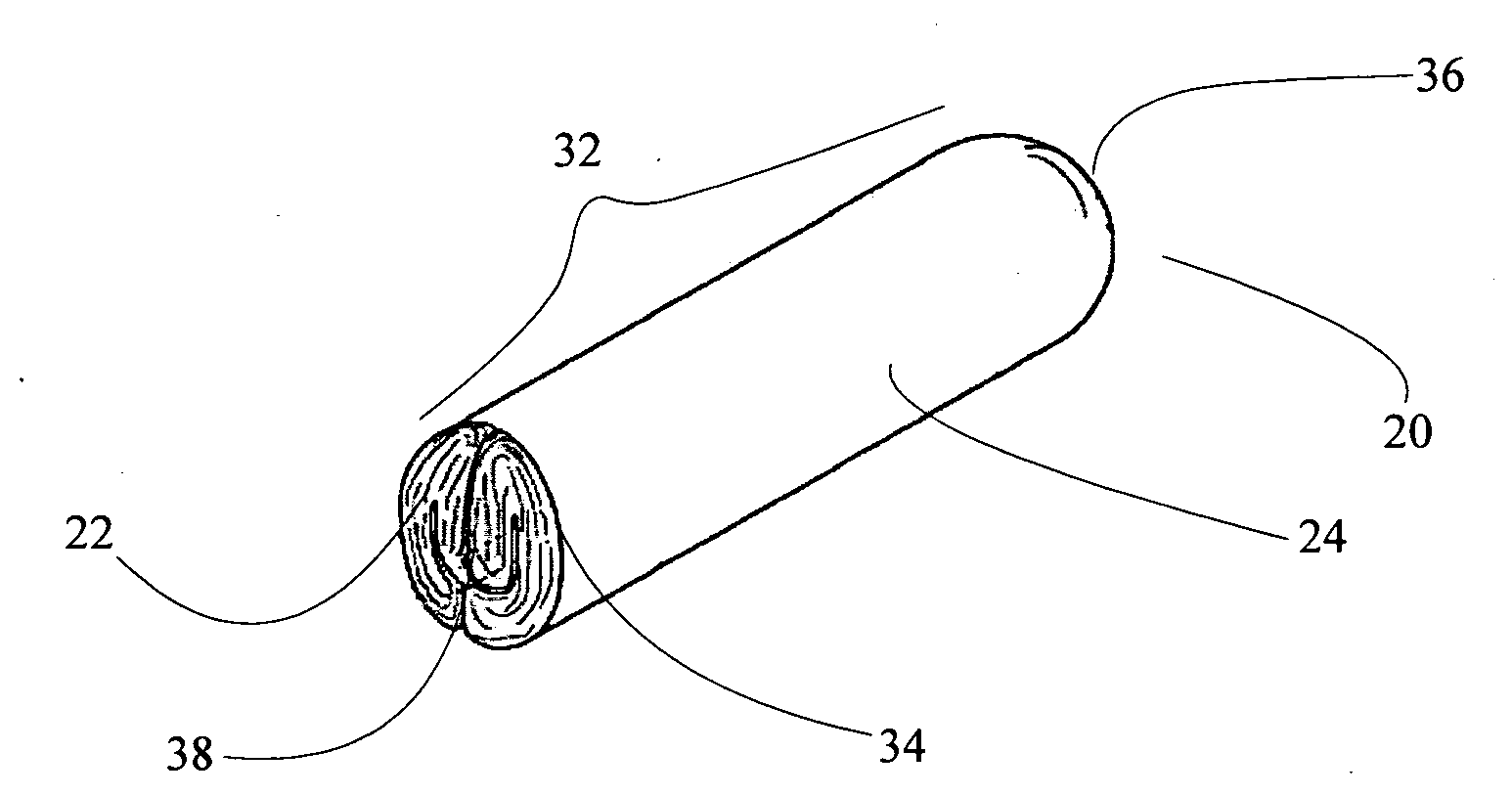
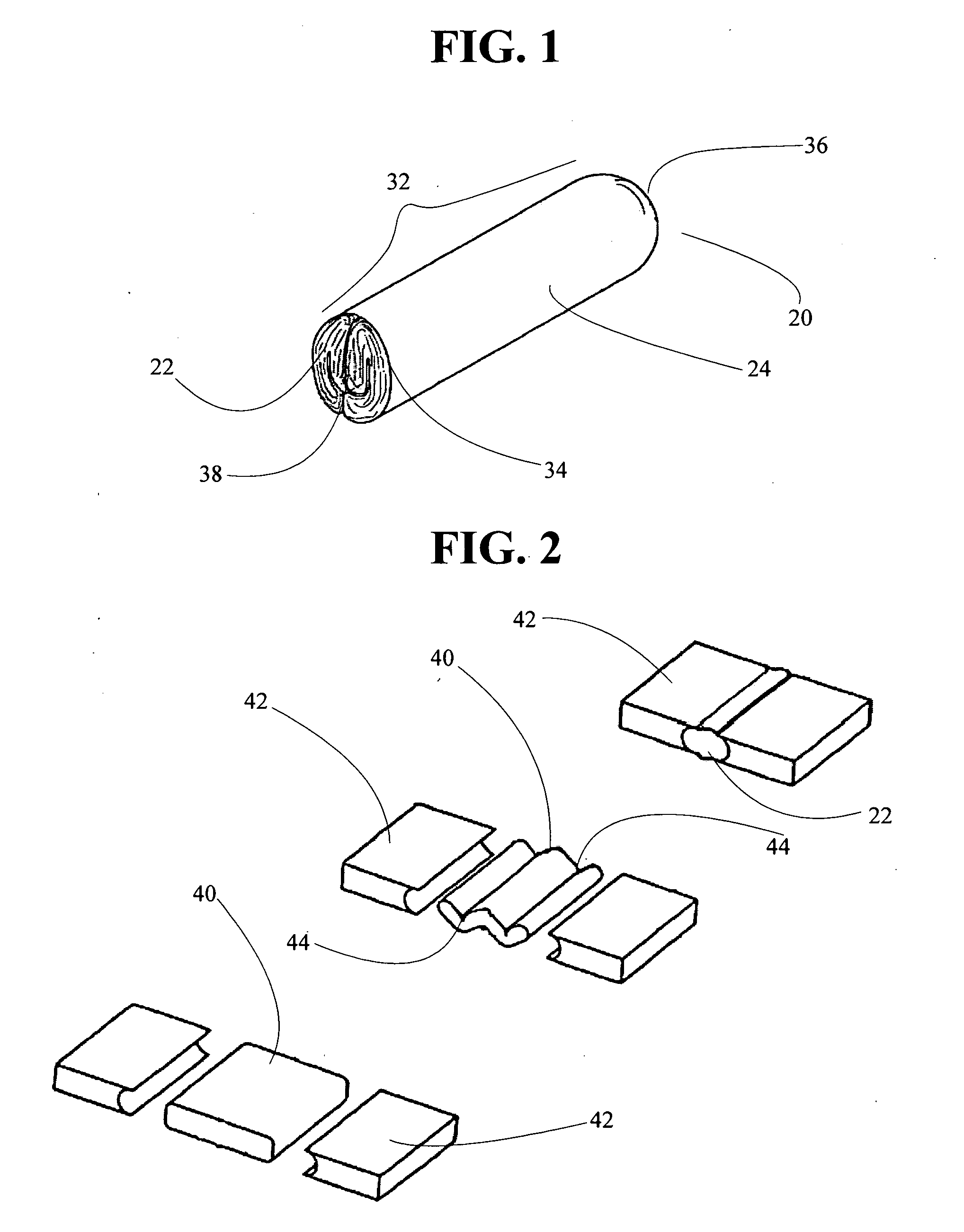
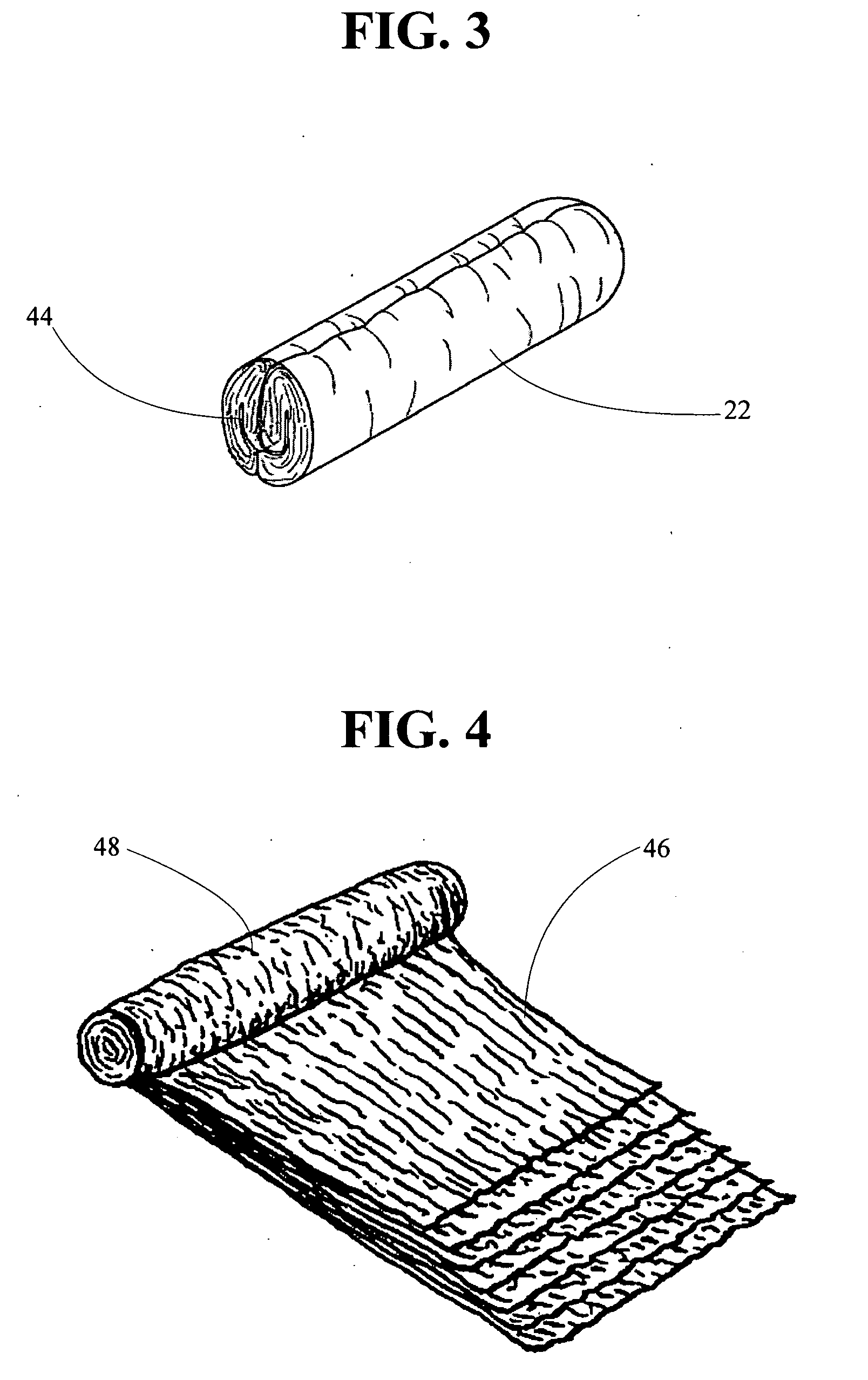
[0039]Referring to FIG. 1, the soft bite block 20 has an axial length 32, a circumference 34 and a first end 36 with an opposed second end 38. The bite block 20 may be any suitable size and thickness which is suitable for insertion in the patient's 30 mouth. The soft bite block 20 is comprised of an inner core 22 comprising a compressed absorbent material, an outer cover 24 comprising at least one layer of material, a...


PUM

PropertyMeasurementUnit
soft biteaaaaaaaaaa
cylindrical massaaaaaaaaaa
perimeteraaaaaaaaaa

Abstract

A soft bite block device for preventing contact between upper and lower teeth of an anesthetized patient. The device includes an elongate roll of cotton gauze encircled by permeable tape so as to maintain the rolled gauze as a monolithic structure. The device is disposable, absorbent and aseptic or sterile. The device is contained within an aseptic or sterile package for the protection of the patient.

Description

BACKGROUND OF THE INVENTION[0001]1. Field of the Invention[0002]The present invention relates generally to a patient airway bite block and, more particularly, to a soft bite block used together with laryngeal mask airways (LMAs), oral endotracheal tubes (ETT), and similar patient airways. The soft bite block is contained within a sterile or aseptic package.[0003]2. Description of Related Art[0004]Patients undergoing general anesthesia must have their airways secured in order to assure adequate ventilation. This is often accomplished through the use of an LMA or an ETT. The LMA functions in place of either a patient face mask or an endotracheal tube. LMAs are comprised of a distal portion which is a cuffed disc-like device which fits around the larynx in the posterior hypopharynx and a more proximal portion which is analogous to an endotracheal tube. LMAs are placed in anesthetized patients blindly and the exiting tube portion is positioned directly in the mid-line of the mouth.[0005...

Claims


Application Information

Patent Timeline
Patent Type & Authority Applications(United States)
IPC IPC(8): A61M16/00A62B9/06B32B38/00
CPCA61B1/24A61M16/0493A61M16/0488
Inventor REIS, NANCYCONDRY, SUSANROLOFF, DIANA
Owner REIS NANCY
Learn More