
Delayed optical router/switch

a delay-type optical router and switch technology, applied in multiplex communication, electromagnetic repeaters, instruments, etc., can solve the problem of slowdown of data traffic incident to the delayed optical router, and achieve the effect of reducing switching performance and high speed

Active Publication Date: 2010-09-16
GWANGJU INST OF SCI & TECH +1
View PDF5 Cites 6 Cited by
  • Summary
  • Abstract
  • Description
  • Claims
  • Application Information

AI Technical Summary

Benefits of technology

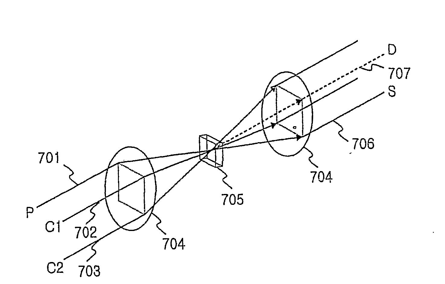
The present invention provides a method for a delayed optical switch / router based on slow light and nondegenerate four-wave mixing processes. The main characteristic of the delayed optical switch is that the switching / routing mechanism is based on quantum coherence, which is strong and can be controlled by another optical field. The slowdown factor is independent of the overall data traffic rate, and the switching bandwidth is constant. The delayed optical router has the function of an optical buffer memory keeping the same data traffic rate with invariant switching / routing bandwidth. The method includes using a nonlinear optical medium interacting with three coherent laser pulses, which form a lambda type or V-type configuration. The laser pulses have different frequencies and timely consecutive ones act as a control pulse to switch and route the input signal. The delayed optical router is composed of at least three-energy levels, and the output direction can be adjusted to be spatially separated each other. The technical effects of the invention include slowing down the data traffic rate without degrading the overall traffic rate, keeping the same data traffic rate with invariant switching / routing bandwidth, and providing an optical buffer memory for faster optical pulses.

Problems solved by technology

At the front interface of it, the data traffic incident to the delayed optical router becomes slow down due to the slow group velocity.

Method used


Image

  • Delayed optical router/switch
  • Delayed optical router/switch
  • Delayed optical router/switch

Examples


Embodiment Construction

[0029]To get a better understanding, reference is now made to the drawings which illustrate the preferred embodiments of the invention.

[0030]Referring to FIG. 1, the delayed optical switch / router of the present invention is shown.

[0031]The delayed optical switch / router comprise at least two laser devices 101a, 101b, and a a nonlinear optical medium 108. The delayed optical switch / router receives three laser inputs 105, 106, and 107, and produces two light outputs 109 and 110. The laser inputs and outputs are connected to the nonlinear optical medium 108 through either fiber, waveguides, or free space.

[0032]A first laser device 101a of the two laser device produce a first laser beam (P) 107, and applies to the nonlinear optical medium 108.

[0033]A second laser device 101b produces a continuous wave or pulsed wave. The second laser device 101b is connected a splitter 102. The splitter 102 splits the continuous wave or pulsed wave into a second laser beam (C1) 105 and a third laser beam...


PUM


Abstract

A system, method, and apparatus for delayed optical router based on slow light and nondegenerate four-wave mixing processes are presented, in which three laser pulses interact with a three-level nonlinear optical medium composing two closely spaced ground states and an excited state. The delayed optical routing mechanism is based on a slow light phenomenon, in which a group velocity of an incoming input signal pulse is slowed down due to quantum coherence induced refractive index change. The two-photon coherence induced on the ground states via electromagnetically induced transparency is optically recovered via nondegenerate four-wave mixing processes. The nondegenerate four-wave mixing generation is enhanced owing to absorption cancellation. In this case, the individual pulse switching / routing time is limited by the coherence decay time that is much faster than population decay time, where the population decay-time is a limiting factor of conventional switching devices. In the present invention of the delayed optical router the overall switching / routing time, however, is controlled to be delayed by using the slow light. Even though the overall switching / routing time can be delayed, the switching bandwidth of the present invention is not degraded at all because the input and output signal's group velocity across the delayed optical router is still same. Therefore, the present invention of the delayed optical router gives an advantage of wide-bandwidth optical data traffic control using a narrow-bandwidth processing unit such as an electronic device. Another advantage is signal amplifications owing to the dark-resonance enhanced nondegenerate four-wave mixing processes.

Description

BACKGROUND OF THE INVENTION[0001]1. Field of the Invention[0002]The present invention relates to a method and apparatus for an optical switch and routing based on quantum coherence, specifically using slow light phenomenon and nondegenerate four-wave mixing processes.[0003]2. Description of the Related Art[0004]An optical router is a switching device applied to convert an optical signal into another one at different propagation direction with either the same frequency basis or not. The optical router is a subcategory of an optical switch that is in general used to drop, add, multiplex, or convert an optical signal into another one. In fiber-optic communications, as more data traffic increases, more information bandwidth is needed. In this case a wider bandwidth optical switch is obviously demanded. However preparation of wide bandwidth optical switch is not simply easy because of technical limitations in switching devices such as an inherently limited optical switching time and slow...

Claims


Application Information

Patent Timeline
Patent Type & Authority Applications(United States)
IPC IPC(8): H04J14/00H04B10/29
CPCG02F1/0126G02F2203/54G02F1/3536G02F1/3515H04B10/00H04B10/25H04B10/29
Inventor HAM, BYOUNG-SEUNG
Owner GWANGJU INST OF SCI & TECH
Learn More