Vehicle control system designed to minimize acceleration shock

Active Publication Date: 2010-09-09
DENSO CORP
View PDF7 Cites 5 Cited by
  • Summary
  • Abstract
  • Description
  • Claims
  • Application Information

AI Technical Summary

Benefits of technology

[0007]It is therefore an object of the invention to provide a vehicle control system for an engine-powered vehicle designed to minimize or absorb acceleration shock occurring upon start of the vehicle without sacrificing the startability of an engine.
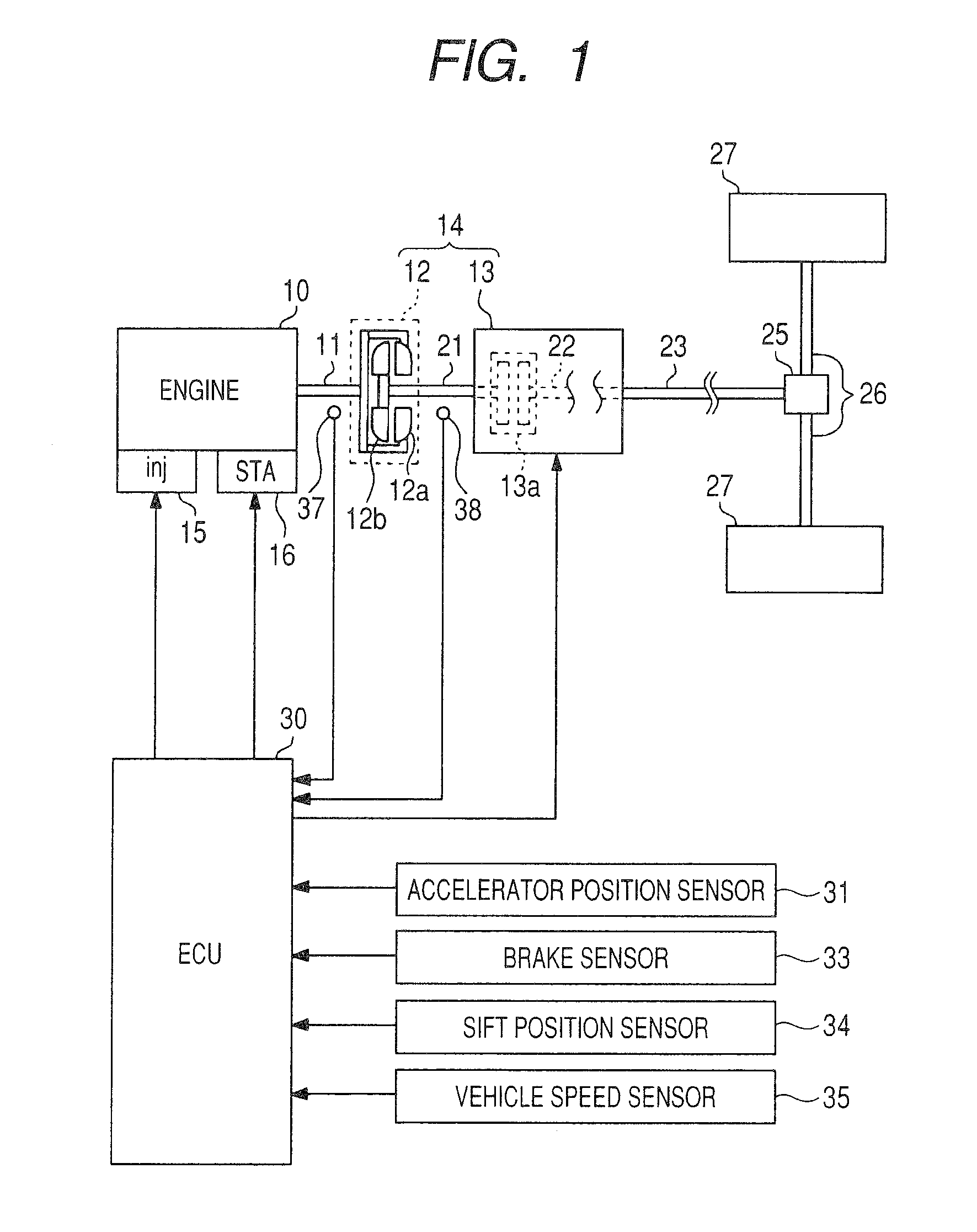
[0011]Consequently, when the engine is restarted, the controller brings the clutch in the automatic transmission into the slippable state based on the speed of the vehicle, as measured by the vehicle speed sensor. In other words, the controller may absorb the torque transmitted to the wheel through the clutch according to the degree of the acceleration shock. The slippage of the clutch serves to absorb the acceleration shock, thus ensuring the startability of the engine as compared with the conventional system, as discussed in the introductory part of this application, which decreases the quantity of fuel to be injected to the engine to decrease or eliminate the acceleration shock.
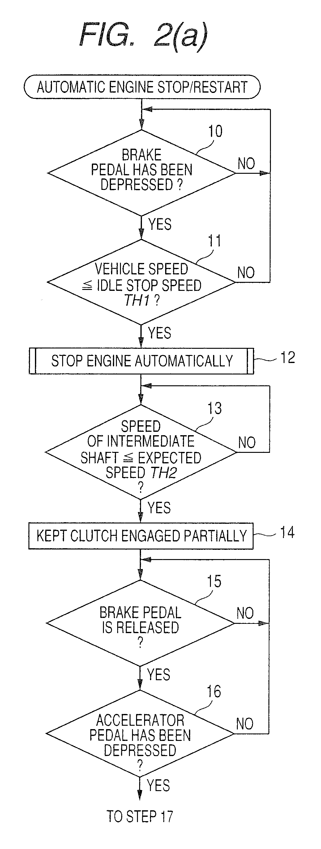
[0014]When the speed of the engine elevated by the restart of the engine has dropped below a peak thereof, the controller enters the clutch control mode to bring the clutch into the slippable state. In typical automatic transmissions equipped with a torque converter, the speed of the input shaft of the automatic transmission rises, and the torque transmitted to the input shaft increases while the speed of the engine is being increased by the restart of the engine. The engagement of the clutch while the speed of the engine is increased by restart of the engine, therefore, result in an increased degree of the acceleration shock. In order to minimize the acceleration shock, the controller, as described above, places the clutch in the slippable state when the speed of the engine has dropped below the peak thereof upon the restart of the engine.
[0017]In typical automatic transmissions equipped with a torque converter, the speed of the input shaft continues to rise while the speed of the engine is being increased by the restart of the engine, so that the speed of the input shaft may rise up to the peak of the speed of the engine upon the restart of the engine. Thus, when the speed of the intermediate shaft is lower than the peak of the speed of the engine elevated by the restart of the engine, there is a possibility that the speed of the input shaft exceeds that of the intermediate shaft, which results in an increased degree of the acceleration shock when the clutch is in engagement upon restart of the engine. Consequently, the controller, as described above, may calculate the peak of speed of the engine elevated by the restart of the engine and place the clutch in one of the slippable state and the disengaged state when the speed of the intermediate shaft is lower than the calculated peak before the engine is restarted. This results in a decreased possibility that the acceleration shock occurs upon the restart of the engine.
[0018]The controller may determine the given speed value based on the calculated peak. This ensures the accuracy in determining a threshold value (i.e., the given speed value) for use in determining whether the clutch is to be placed in the slippable state or not.
[0019]When a condition in which the speed of the vehicle, as measured by the vehicle speed sensor, is lower than a given speed value is met upon restart of the engine, the controller places the clutch in the slippable state. In other words, when the speed of the vehicle is relatively high meaning that there is the low possibility that the acceleration shock occurs, the controller does not place the clutch in the slippable state, thereby increasing the number of times the engine torque needed to enable the vehicle to run is transmitted to the wheel quickly, which results in an increase in service life of the clutch.

Problems solved by technology

When the given engine restart requirement is met with the automatic transmission placed in the travel gear range after stop of the engine, and the engine has been restarted, an increase in degree of the torque outputted from the engine may result in the acceleration shock.
When the speed of the input shaft exceeds that of the output of the clutch upon restart of the engine, it may result in the acceleration shock.

Method used


Image

  • Vehicle control system designed to minimize acceleration shock
  • Vehicle control system designed to minimize acceleration shock
  • Vehicle control system designed to minimize acceleration shock

Examples


Embodiment Construction

[0026]Referring to the drawings, particularly to FIG. 1, there is shown a vehicle control system according to the invention which is installed in an automotive vehicle equipped with an internal combustion engine 10 and an automatic transmission 14.

[0027]The automatic transmission 14 includes a torque converter 12 and a gearbox 13. The gearbox 13 is coupled to the crankshaft 11 (i.e., an output shaft) of the engine 10 through the torque converter 12. The engine 10 is, for example, a multi-cylinder gasoline engine and equipped with injectors 15 and spark plugs, one for each cylinder thereof. The engine 10 has installed thereon a starter 16 to crank or give initial rotation to the engine 10 when it is required to start the engine 10. The engine 10 may alternatively be a diesel engine.

[0028]The torque converter 12 is made up of a pump impeller 12a coupled to the crankshaft 11, a turbine impeller 12b coupled to an input shaft 21 of the gearbox 13, and a one-way clutch, etc,. The turbine ...


PUM


Abstract

A vehicle control system for an engine-powered vehicle equipped with an engine and an automatic transmission with a clutch. When a given engine stop requirement is met during running of the engine, the system stops the engine automatically. When a given engine restart requirement is met after stop of the engine, the system restarts the engine and enters a clutch control mode to bring the clutch in the automatic transmission into a slippable state in which the clutch is permitted to slip based on the speed of the vehicle, thereby absorbing the acceleration shock which usually occurs upon engagement of the clutch to transmit engine torque to wheels of the vehicle when the engine is restarted, and the speed of the vehicle is relatively low.

Description

CROSS REFERENCE TO RELATED DOCUMENT[0001]The present application claims the benefit of Japanese Patent Application No. 2009-50119 filed on Mar. 4, 2009, the disclosure of which is incorporated herein by reference.BACKGROUND OF THE INVENTION[0002]1. Technical Field of the Invention[0003]The present invention relates generally to a vehicle control system designed to stop and restart an engine automatically which is mounted in an automotive vehicle equipped with an automatic transmission, and more particularly, to such a vehicle control system designed to minimize or absorb acceleration shock occurring upon start of the vehicle.[0004]2. Background Art[0005]There are some of the above type of vehicle control systems which are designed to suppress an acceleration shock arising from transmission of engine torque to an axle of the vehicle when the engine is restarted with the automatic transmission placed in the drive (D) range. For example, Japanese Patent First Publication No. 2001-55943...

Claims


Application Information

Patent Timeline
IPC IPC(8): G06F19/00B60W10/10B60W30/18F02D29/00F02D29/02F16H59/74F16H61/02F16H61/686F16H63/50
CPCB60W10/02B60W10/06B60W30/192B60W2510/1015B60W2520/10B60W2710/022Y10T477/6403F02D17/04F02D29/02Y02T10/48Y10T477/6422Y10T477/638Y10T477/26B60W2710/025Y02T10/40
Inventor SAITO, TATSUYA
Owner DENSO CORP
Why Eureka
Try Eureka