Devices Comprising Delay Line for Applying Variable Delay to Clock Signal

a delay line and clock signal technology, applied in pulse generators, pulse manipulation, pulse techniques, etc., can solve the problems of restricting the amount of data the controller has to interpret, and achieve the effect of reducing power consumption and adversely affecting switching speed

Inactive Publication Date: 2010-09-09
INTERUNIVERSITAIR MICRO ELECTRONICS CENT (IMEC VZW)
View PDF5 Cites 19 Cited by
  • Summary
  • Abstract
  • Description
  • Claims
  • Application Information

AI Technical Summary

Benefits of technology

[0005]It is an aim of the invention to provide a device having a delay line for applying a variable delay to a

Problems solved by technology

This severely restrict the amount of data which the controller has to interpre

Method used


Image

  • Devices Comprising Delay Line for Applying Variable Delay to Clock Signal
  • Devices Comprising Delay Line for Applying Variable Delay to Clock Signal
  • Devices Comprising Delay Line for Applying Variable Delay to Clock Signal

Examples


Embodiment Construction

[0034]The present invention will be described with respect to particular embodiments and with reference to certain drawings but the invention is not limited thereto but only by the claims. The drawings described are only schematic and are non-limiting. In the drawings, the size of some of the elements may be exaggerated and not drawn on scale for illustrative purposes. The dimensions and the relative dimensions do not correspond to actual reductions to practice of the invention.

[0035]Furthermore, the terms first, second, third and the like in the description and in the claims, are used for distinguishing between similar elements and not necessarily for describing a sequential or chronological order. The terms are interchangeable under appropriate circumstances and the embodiments of the invention can operate in other sequences than described or illustrated herein.

[0036]Moreover, the terms top, bottom, over, under and the like in the description and the claims are used for descriptiv...


PUM


Abstract

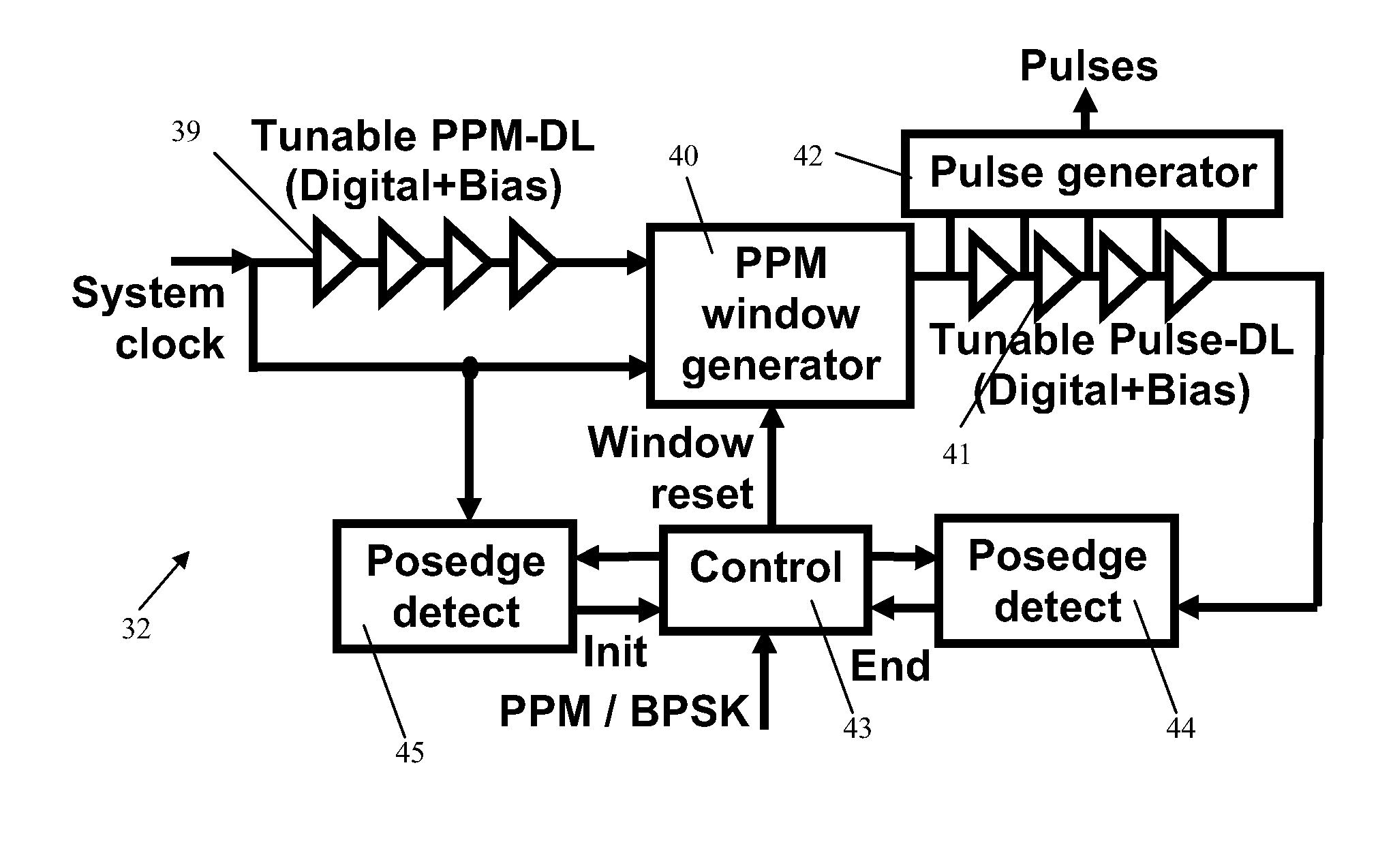
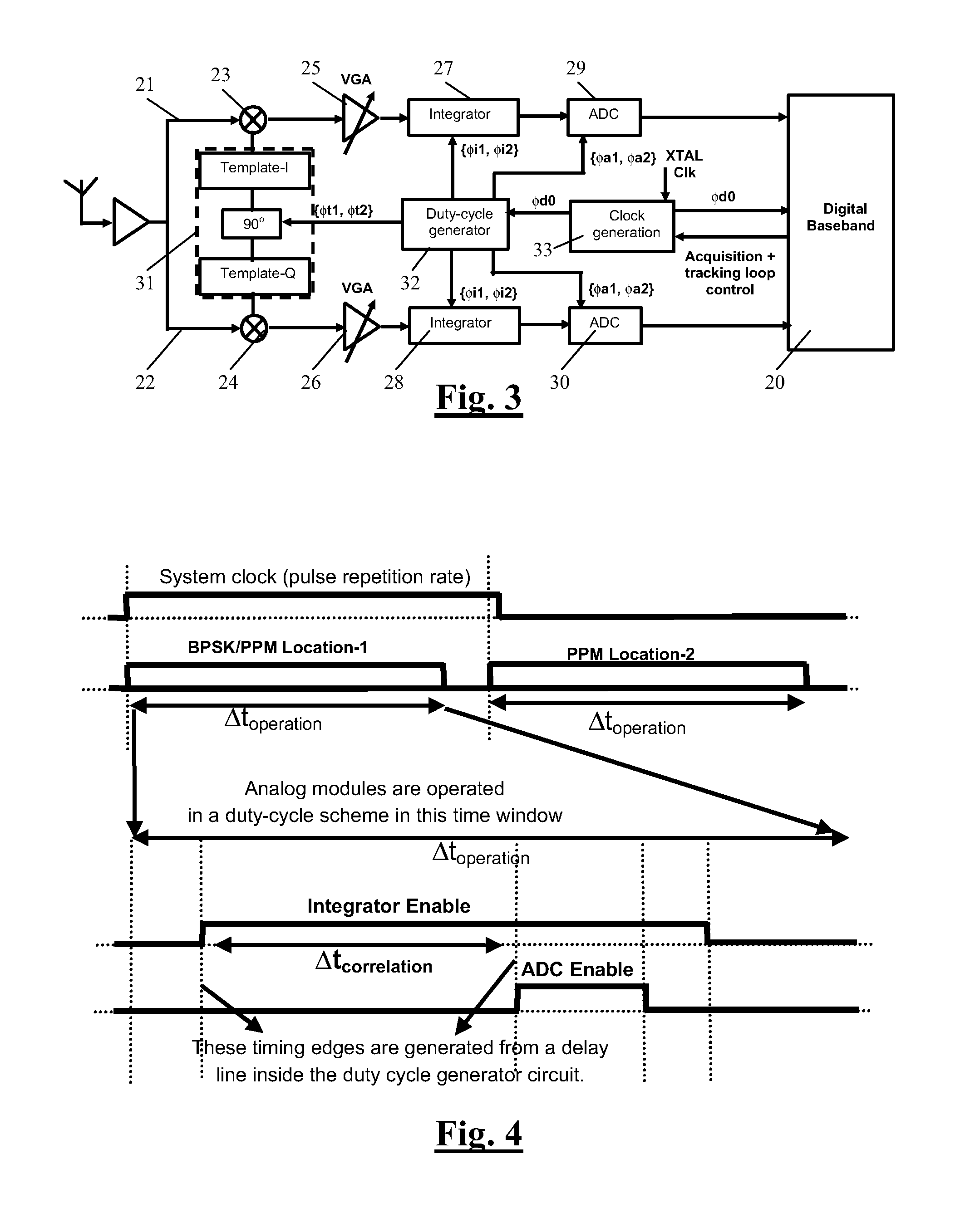
The disclosure relates to a device comprising at least one delay line for applying a variable delay to a clock signal and a controller for controlling the variable delay of the delay line. Each delay line comprises a plurality of concatenated delay banks which provide different delay values with respect to each other, a bypass parallel over each of said the delay banks, and switching elements associated with each of the delay banks for selecting either the respective delay bank or the respective bypass. Each of the delay banks is provided with a delay bank status indicator for indicating propagation of the clock signal through the delay bank towards the controller. The controller is provided for taking the indicated propagation of the clock signal into account upon setting said switching elements. Devices according to this disclosure are, amongst other uses, suited for use in Ultra Wide Band (UWB) receiving or transmitting devices, in particular those devices, designed for low power consumption, by enabling power on and off switching of parts of such devices as analog to digital converters and integrators, during timing windows.

Description

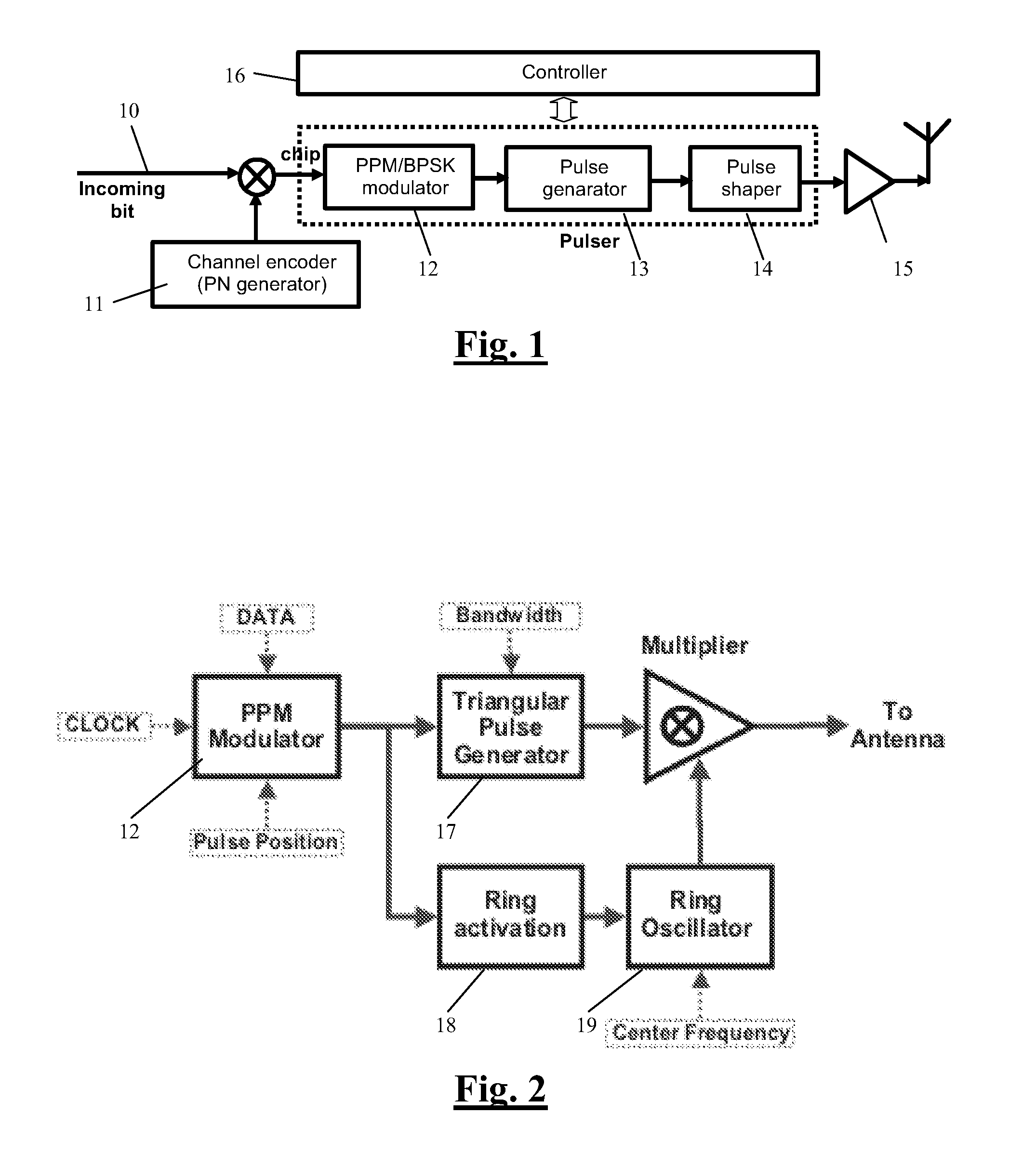
TECHNICAL FIELD[0001]The invention relates to devices using a delay line for applying a variable delay to a clock signal, for example for synchronizing the clock signal to a data signal. The device can for example be an Ultra Wide Band (UWB) receiving or transmitting device, in particular those devices, designed for low power consumption, by enabling power on and off switching of parts of said device like analog to digital converters and integrators, during timing windows.BACKGROUND ART[0002]The Federal Communications Commission (FCC) has authorized ultra-wide-band (UWB) communication between 3.1 GHz and 10.6 GHz. Since UWB pulses rely on ultra-short (nanosecond scale) waveforms to have UWB spectral occupancy, UWB radios come with unique advantages: i) enhanced capability to penetrate through obstacles; ii) ultra high precision ranging at the centimeter level; iii) potential for very high data rates along with high user capacity; and iv) smaller circuit sizes with less power consump...

Claims


Application Information

Patent Timeline
IPC IPC(8): H03L7/06H03K3/017
CPCH03K5/131H03K5/133H04B1/7183H03K7/04
Inventor BADAROGLU, MUSTAFA
Owner INTERUNIVERSITAIR MICRO ELECTRONICS CENT (IMEC VZW)
Why Eureka
Try Eureka