Ultrasonic wave measuring method and apparatus
a technology of ultrasonic waves and measuring methods, applied in the direction of instruments, specific gravity measurement, processing detected response signals, etc., can solve the problems of large thickness of interfaces and difficulty in quality (good or bad) determination, and achieve the effect of high accuracy
- Summary
- Abstract
- Description
- Claims
- Application Information
AI Technical Summary
Benefits of technology
Problems solved by technology
Method used
Image


Examples
first embodiment
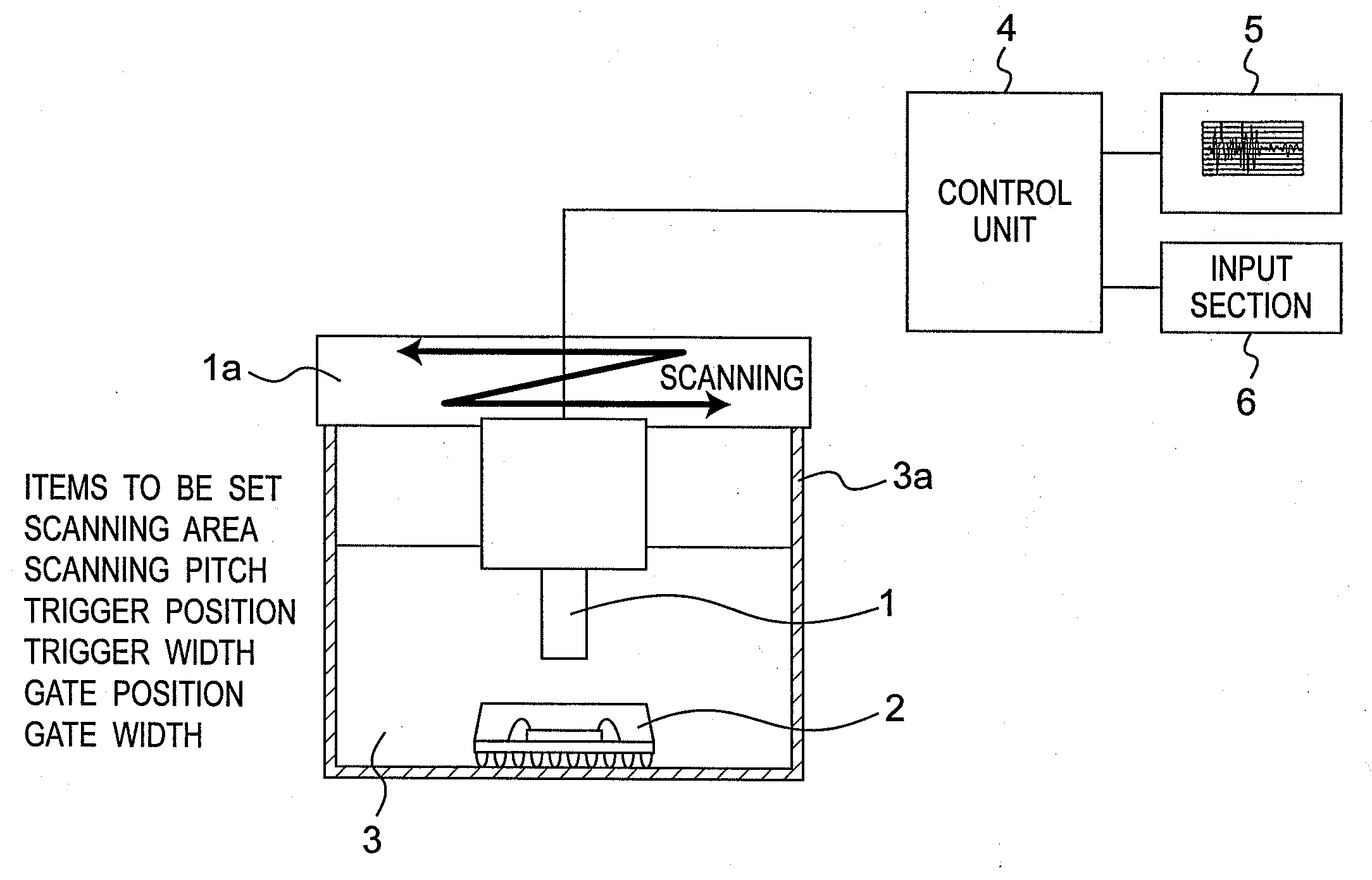
[0078]FIG. 1A, FIG. 1B, and FIG. 1C are views showing a detailed configuration of an ultrasonic wave measuring apparatus for performing quality (good or bad) determination according to a first embodiment of the present invention, a control unit of the ultrasonic wave measuring apparatus, and a flowchart showing a process of an ultrasonic wave measuring method using the ultrasonic wave measuring apparatus.
[0079]The ultrasonic wave measuring apparatus of FIG. 1A is configured including an ultrasonic probe 1, an ultrasonic probe drive unit 1a, a control unit 4, and an input section 6. In FIG. 1A, the scanning area listed as an item to be set refers to setting what range of the sample to measure (XY plane position). For instance, entire surface of the sample, or one part of the sample (see scanning area 2Sa of sample 2, which is a first example of the scanning area of FIG. 1G), or a plurality of areas (see scanning areas 2Sb of sample 2, which is a second example of the scanning area of...
second embodiment
[0127]An ultrasonic wave measuring method and an apparatus therefor according to a second embodiment of the present invention will be described below.
[0128]Determination may be difficult in some cases in the determination method described in the first embodiment. If the range of variation of the correlation coefficient value is the range of the correlation coefficient value of the acceptable article and the defective article such as if the variation is large in the correlation coefficient value by the set long interval master data, the determination is not possible. The reason may be that the length of the master data is inappropriate, or that information other than OK / NG of the interface is contained in excess.
[0129]For instance, the master data width in FIG. 4 is 400 ns, but if the magnitude of one wave is about 60 ns and the change in waveform in time of defect is worth one wave, the master data contains an overly excessive waveform component. In this case, even if defect occurs ...
third embodiment
[0154]A third embodiment of the present invention will now be described. In the third embodiment, a determination method by the conventional gate method will be described using the time phase correction with the long interval master data, which is the first stage described in the second embodiment.
[0155]As shown in FIG. 16, in the conventional gate method as described in the background art, the trigger 11 is applied to the surface wave, the gate 12 is set to the waveform position to observe with the position applied with the trigger 11 as the zero reference, comparison with the zero reference is carried out by the waveform component in the gate 12, and quality determination of an observed object 102 is performed. That is, the time correction of the waveform is performed by the trigger 11 of the surface wave. However, as described in the “Issues to be solved by the Invention”, temporal shift may occur even in the waveform after the trigger 11 by the surface wave as shown in FIG. 19, ...
PUM
 Abstract
Description
Claims
Application Information
 - R&D
- Intellectual Property
- Life Sciences
- Materials
- Tech Scout
- Unparalleled Data Quality
- Higher Quality Content
- 60% Fewer Hallucinations
Browse by: Latest US Patents, China's latest patents, Technical Efficacy Thesaurus, Application Domain, Technology Topic, Popular Technical Reports.
© 2025 PatSnap. All rights reserved.Legal|Privacy policy|Modern Slavery Act Transparency Statement|Sitemap|About US| Contact US: help@patsnap.com