
Wind turbine blade, wind turbine and method for manufacturing a wind turbine blade

a technology of wind turbine blades and wind turbine blades, which is applied in the direction of wind motors with parallel air flow, non-positive displacement fluid engines, liquid fuel engine components, etc., can solve the problems of lightning current following the electrical cables to a ground potential instead of the down conductor, time-consuming and costly repair of the sensor system, and difficult protection

Inactive Publication Date: 2010-09-02
VESTAS WIND SYST AS
View PDF10 Cites 17 Cited by
  • Summary
  • Abstract
  • Description
  • Claims
  • Application Information

AI Technical Summary

Benefits of technology

[0012]Hereby it is achieved a galvanic separation between the electric power modules and any electric ground potential by using light beams as the energy source and converting the energy source locally at the modules to electric power. The lightning current will thus not affect or damage the electric powered modules due to the galvanic separation.
[0028]According to an even further aspect of the invention, in the production of wind turbine blades, if the light guides are casted in the blade structure, a larger uniformity between each individually produced blade could be obtained. This could e.g. ease calculations on the optical fibers etc. because the length of the optical fibers in each blade is the same. Furthermore the production of wind turbine blade may be optimized because of light guides in a desired predetermined length could be provided.

Problems solved by technology

A problem with the use of internal electrical cables for sensors and a lightning protection system in the wind turbine blade is the risk of lightning current following the electrical cables to a ground potential instead of the down conductor after a lightning flashover.
Even if a flashover does not occur when the lightning strikes the wind turbine blade another problem may arise by the electromagnetic interference between the lightning down conductor and the sensor systems.
The result of the abovementioned lightning situations may be time consuming and costly repair of the sensor systems.
The sensor modules would otherwise be very difficult to protect against the effects of the lightning current without increasing the size of the modules significantly and thus be restricted in the positioning of the sensor modules within the blade.
Having more than one optical fibre may provide a redundancy to the system, which is preferable because it is difficult to replace damaged optical fibres in the wind turbine blade.
Hence the risk of damaging the light guide when e.g. a sensor or other equipment has to be maintained or replaced in the blade is eliminated.

Method used


Image

  • Wind turbine blade, wind turbine and method for manufacturing a wind turbine blade
  • Wind turbine blade, wind turbine and method for manufacturing a wind turbine blade
  • Wind turbine blade, wind turbine and method for manufacturing a wind turbine blade

Examples


Embodiment Construction

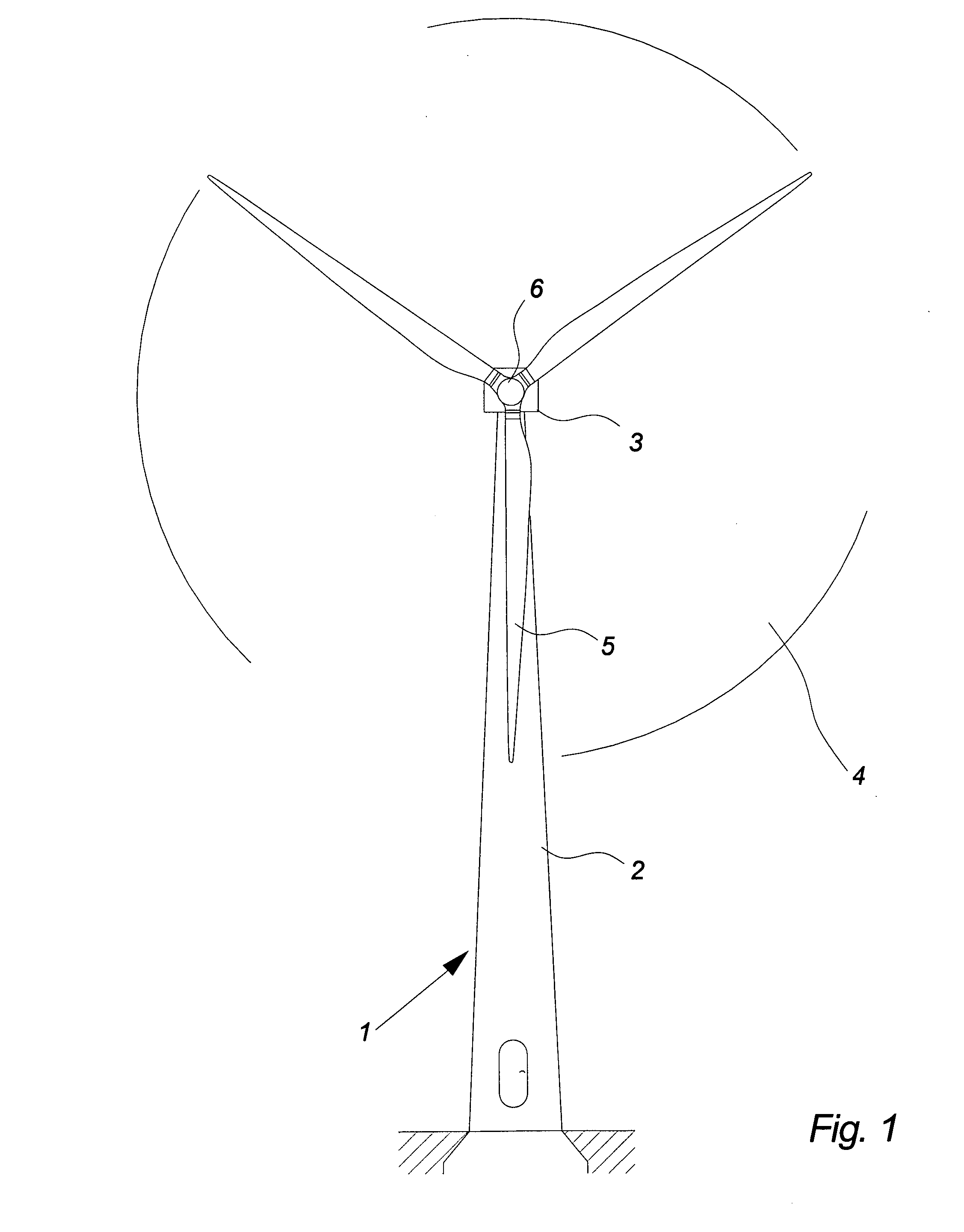
[0042]FIG. 1 illustrates a wind turbine 1, comprising a tower 2 and a wind turbine nacelle 3 positioned on top of the tower 2. The wind turbine rotor 4 comprises at least one wind turbine blade e.g. three wind turbine blades 5 as illustrated in the figure. The rotor is mounted on a hub 6, which is connected to the nacelle 3 through the low speed shaft extending out of the nacelle front.

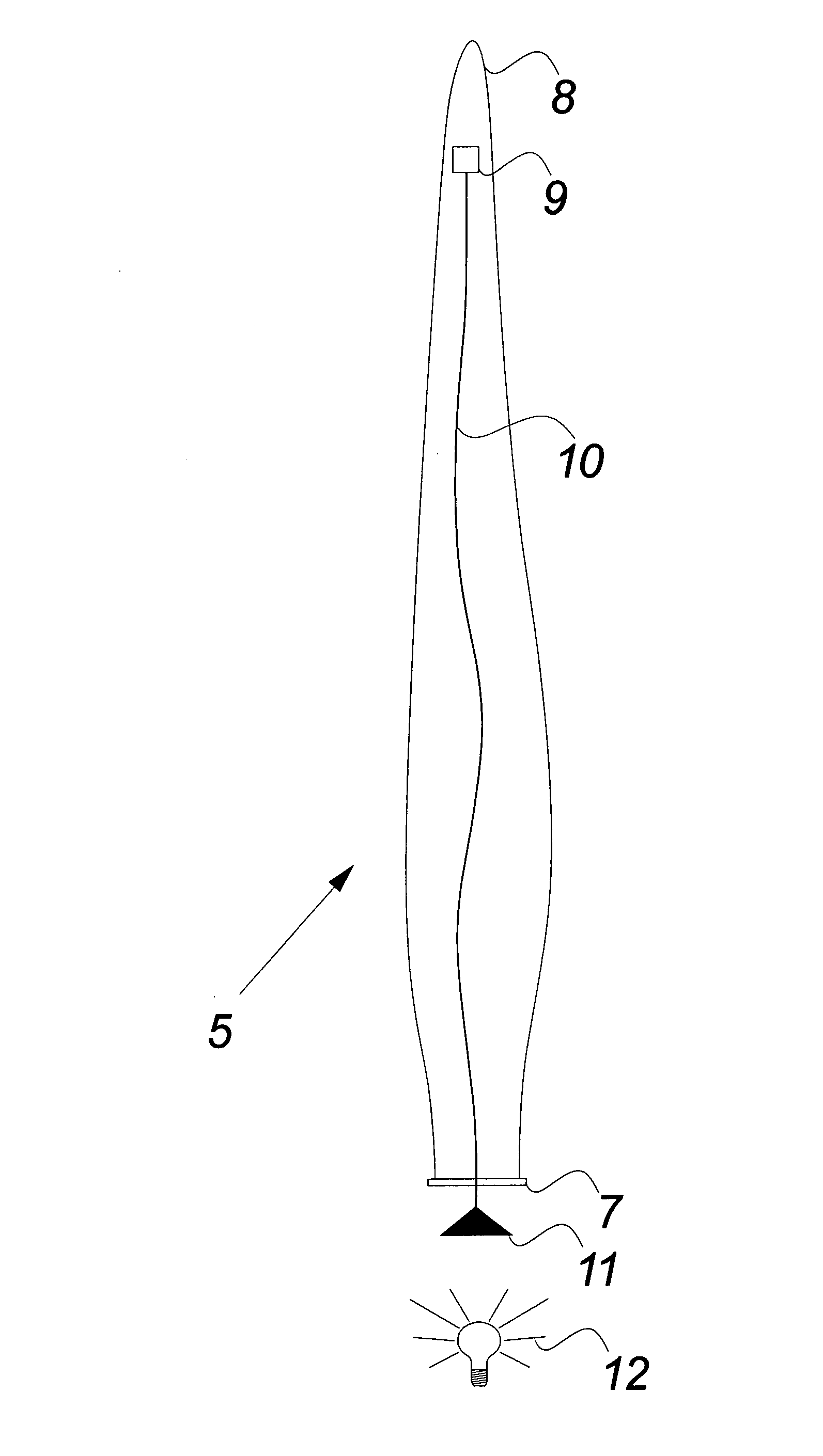
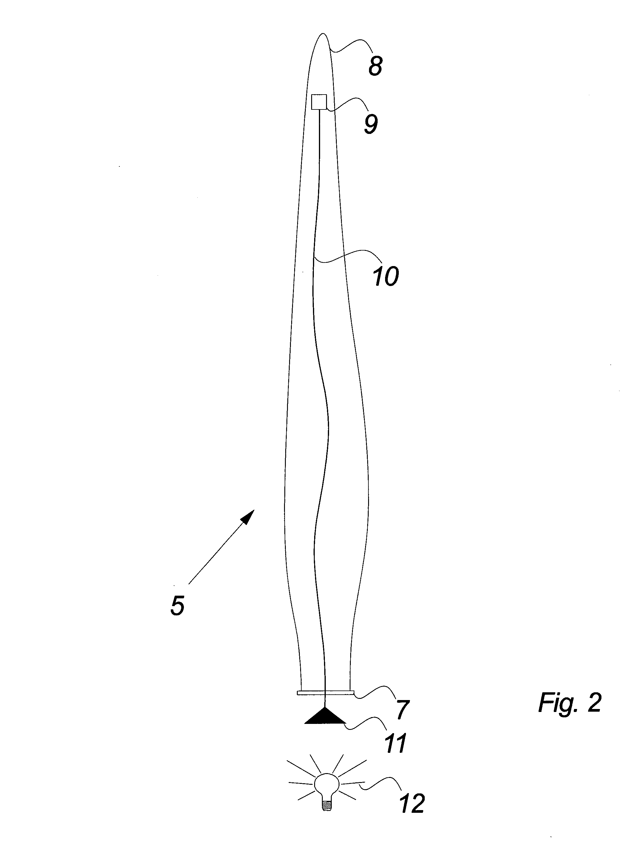
[0043]FIG. 2 illustrates schematically a wind turbine blade according to the invention.

[0044]The figure especially illustrates the optical fibre connection 10 between a light source 12 positioned outside the wind turbine blade 5 and an electric powered module 9 positioned in or inside the wind turbine blade 5.

[0045]The light source 12 may for example be positioned in the hub 6 or in the nacelle 3 (not illustrated in the figure) and facing one end 11 of the optical fibre 10. The light source may be any kind of light source with the possibility of emitting light of a certain and defined power density e....


PUM

PropertyMeasurementUnit
Electrical conductivityaaaaaaaaaa
Transmissionaaaaaaaaaa
Energyaaaaaaaaaa

Abstract

The invention relates to a wind turbine blade comprising one or more electric powered modules. The modules have power supply means converting an energy source to electrical power for said one or more modules, wherein said energy source is light beams transmitted to the power supply means in the blade structure and / or interior from an external light source. The invention also relates to wind turbine and a method for manufacturing a wind turbine blade.

Description

BACKGROUND OF THE INVENTION[0001]The invention relates to a wind turbine blade, wind turbine and a method for manufacturing a wind turbine blade.[0002]Modern wind turbine blades hold different apparatuses in order to survey and protect the blades from overload and damage such as sensor means. The sensor means are usually externally supplied with electrical power via electrical cables running through the interior of the blade.[0003]Wind turbine blades may also comprise a lightning protection system which usually includes a number of lightning receptors e.g. on the blade tip surface and with connections to a lightning down conductor. The lightning down conductor runs through the interior of the blade and via other parts of the wind turbine to a ground potential.[0004]A problem with the use of internal electrical cables for sensors and a lightning protection system in the wind turbine blade is the risk of lightning current following the electrical cables to a ground potential instead o...

Claims


Application Information

Patent Timeline
IPC IPC(8): F03D9/00F03D11/00B23P15/04
CPCF03D1/065F03D11/00F03D11/0033F05B2260/80Y10T29/49337Y02E10/722Y02E10/726B23P15/04F03D9/002Y02E10/721F03D80/00F03D80/30F03D9/25Y02E10/50Y02E10/72Y02P70/50F03D9/007F03D17/00H02S10/12
Inventor NIEUWENHUIZEN, JOHN JOHANNES MATHIAS HUBERTUS
Owner VESTAS WIND SYST AS
Learn More