Eureka AIR delivers breakthrough ideas for toughest innovation challenges, trusted by R&D personnel around the world.

Steerable phase array antenna RFID tag locater and tracking system and methods

a phase array antenna and locater technology, applied in the direction of electric signalling details, instruments, using reradiation, etc., can solve the problems of inability to locate or track multiple rfid tags in a particular location or volume, inherently difficult to locate or track, and the accuracy of conventional rfid readers is not acceptable, and the accuracy of conventional systems cannot be achieved. , to achieve the effect of tracking the three-dimensional movement of rfid tags, the accuracy o

Active Publication Date: 2010-08-19
RF CONTROLS
View PDF12 Cites 49 Cited by
  • Summary
  • Abstract
  • Description
  • Claims
  • Application Information

AI Technical Summary

Benefits of technology

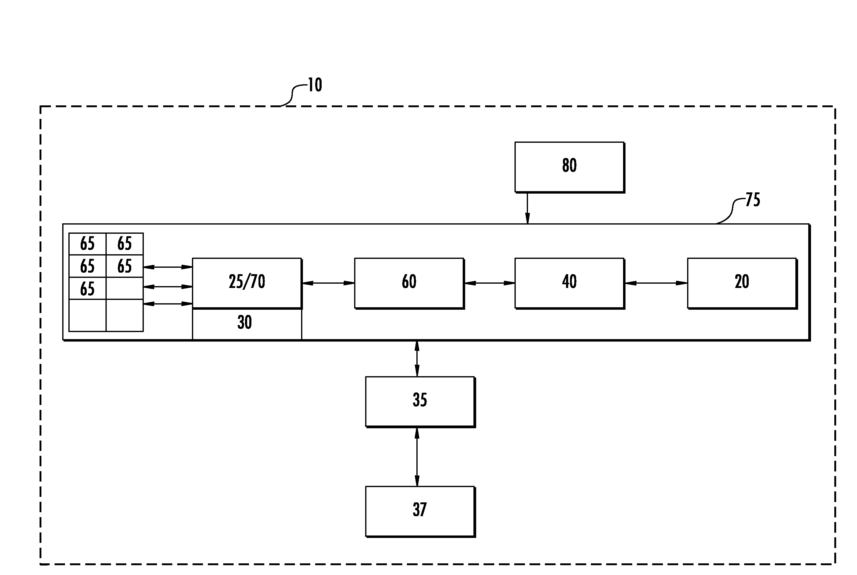
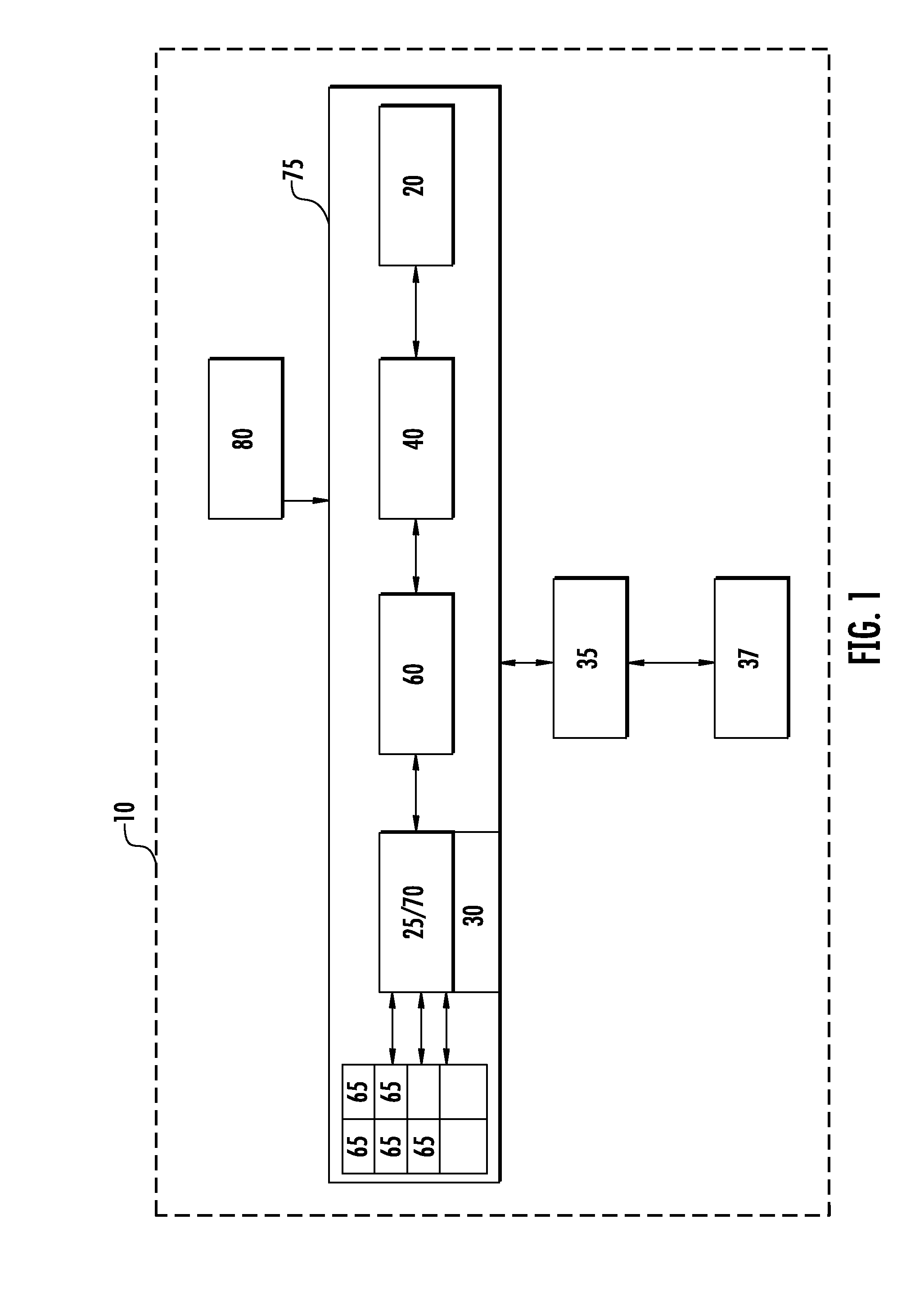
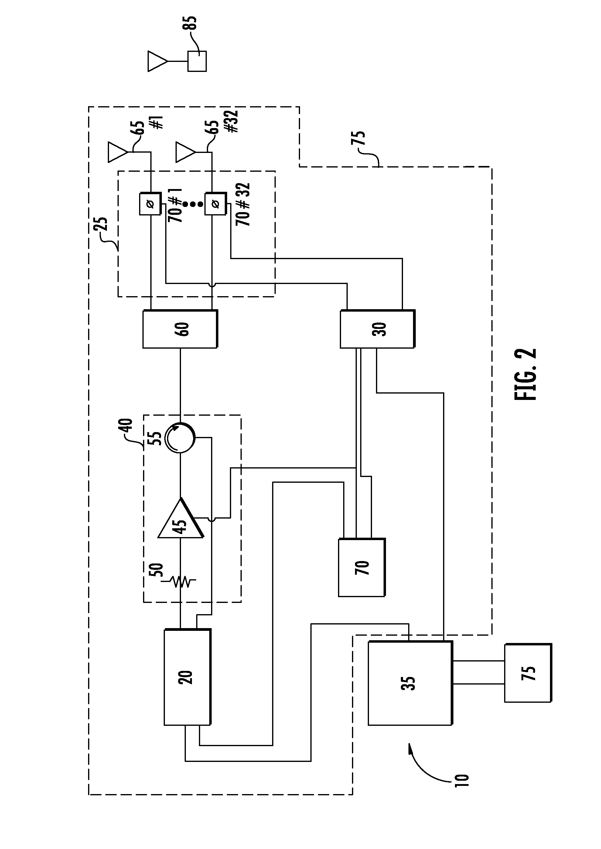
[0019]To improve manufacturing efficiencies, significantly simplify system installation and or for ease of system configuration, elements of the system may be integrated to form a signal acquisition and source location module (SASL) 75 that incorporates the phase array steerable antenna 15, beam steering unit 25 and beam steering controller 30 into a single module. Alternatively, the SASL 75 may also include the RFID reader 20 operative to transmit an interrogation signal beam on a desired frequency or frequency band and to receive one or more response signals on a desired frequency or frequency band via the phase array steerable antenna. The interrogation signal and response signal frequency(s) and or frequency band(s) may be configured to a common frequency or frequency band according to the signal parameters the system is configured for use with.
[0030]Because the second SASL 75 scans a subset of its operating environment 90, guided by the first SASL 75 result, the number of direction vectors stepped through and thus the overall scan time is significantly reduced.
[0034]As the data matrix is updated and projected tag locations stored with respect to ongoing scans, changes in projected tag locations may be analyzed to identify RFID tags that are in motion, including speed and direction. Error correction may be applied to the data matrix origin location patterns, such as iterative weighted robust least squares estimation to improve the accuracy of trajectory estimates, from which directional tracking may be derived via derivatives of the trajectory results.
[0047]One skilled in the art will recognize that the present invention provides numerous advantages, besides the method(s) of operation herein above, including the ease of installation and greatly simplified power and or communications interconnection requirements provided by the SASL 75 according to the invention.
[0048]Another advantage of the present invention is flexibility realized by the ease with which multiple SASL 75 may each be utilized under the direction of a central control computer 35 to increase the size of the overall area being monitored, to provide additional data points for improving the accuracy of the triangulation calculations and also to increase the number of interrogation signals and thereby the resulting signal power level that may be focused upon a single point in space.
[0049]Still another advantage of the present invention is to provide the combination of a steerable phase array antenna and an RFID reader to generate a radio frequency (“RF”) to interrogate and read RFID tags, to achieve significantly improved multipath immunity.Table of Parts10intelligent tracking and control system15phase array steerable antenna20RFID reader25beam steering unit30beam steering unit controller35control computer37operator interface40amplification subsystem45amplifier50attenuator55circulator60power splitter / combiner65antenna element70phase shifter75signal acquisition and source location module77network switch80power supply85RFID tag90operating environment

Problems solved by technology

Multiple RFID tags in a particular location or volume, such as a warehouse, are inherently difficult to locate or track.
When RFID tags are in proximity to one another (the proximity varying, for example, due to RFID tag type or conditions within the space in which they are located or conditions in the surrounding space or both), that is a multipath environment, conventional RFID readers cannot locate the RFID tags with acceptable precision.
Furthermore, conventional systems cannot track the three dimensional movement of RFID tags with any precision, if at all.

Method used


Image

  • Steerable phase array antenna RFID tag locater and tracking system and methods
  • Steerable phase array antenna RFID tag locater and tracking system and methods
  • Steerable phase array antenna RFID tag locater and tracking system and methods

Examples


Embodiment Construction

[0012]The inventor has developed an RF signal intelligent tracking and control system (ITCS) 10, for example as generally shown in FIG. 1 and in higher detail in FIGS. 2 and 3, including a phase array steerable antenna 15; an RFID reader 20 in operative communication with the phase array steerable antenna 15; a beam steering unit (BSU) 25, in operative communication with the phase array steerable antenna 15; a BSU controller 30 in operative communication with the BSU 25; and a control computer 35 in operative communication with the BSU controller 30. An operator interface 37, such as a display and or control panel may be coupled to the control computer 35. The operator interface 37 may be local to the installation or remotely coupled, via a proprietary network and or the internet.

[0013]The phase array steerable antenna 15 is comprised of at least one antenna element 65, for example a circularly polarized patch antenna element 65, and preferably includes a plurality of circularly pol...


PUM


Abstract

A system for and method of tracking and locating RFID tags, including where at least one steerable phase array antenna may locate the tags associated with items in three dimensions in real time, through the use of a beam steering unit and controller therewith to control the direction of a beam launched by the at least one steerable phase array antenna.

Description

CROSS REFERENCE TO RELATED APPLICATIONS[0001]This application claims the benefit of U.S. Provisional Patent Application No. 60 / 993,418, titled “Steerable Phase Array Antenna RFID Tag Locator and Tracking System”, filed by Graham P. Bloy on Sep. 11, 2007 and International Patent Application No.: PCT / IB2008 / 053643, titled “Steerable Phase Array Antenna RFID Tag Locater and Tracking System and Methods”, filed by Graham P. Bloy on Sep. 9, 2008, both applications hereby incorporated by reference in their entirety.FIELD OF THE INVENTION[0002]The present invention relates to a steerable phase array antenna RFID tag locater and tracking system. More particularly, the system comprising at least one steerable phase array antenna, RFID reader and a controller to acquire, locate and track RFID tags.BACKGROUND OF THE INVENTION[0003]Conventional RFID readers can read tags at distances less than desired by the RFID tag user. Multiple RFID tags in a particular location or volume, such as a warehous...

Claims


Application Information

Patent Timeline
IPC IPC(8): H04Q5/22H01Q3/00
CPCG01S5/0215G01S5/04G01S5/12G01S13/76G01S13/878G08B13/2462G06K2017/0045H01Q1/2216H01Q3/36G06K7/01G06K7/10079G01S5/0218
Inventor BLOY, GRAHAM P.
Owner RF CONTROLS
Why Eureka
Eureka Blog
Learn More