
Method for automatically producing a conglomerate structure and apparatus therefor

a technology of automatic production and conglomerate structure, applied in the field of building industry, can solve the problems of increasing supply and handling costs, affecting the effect of requiring relevant labour and transportation costs, so as to achieve the effect of enhancing the method in the practi

Inactive Publication Date: 2010-08-19
DINI ENRICO
View PDF7 Cites 65 Cited by
  • Summary
  • Abstract
  • Description
  • Claims
  • Application Information

AI Technical Summary

Benefits of technology

[0010]The present invention proposes some important improvements and innovations to the above described method for automatically making building structures and monolithic masonry constructions, in order to reduce the problems related to the need of a containing walls for the granular material, such that the effectiveness of the method in the practice is enhanced.

Problems solved by technology

A drawback of such method is the need of raising the side walls before laying the stone-like regions, and the disassembly of the walls after hardening, which requires relevant labour and transport costs due to the walls weight and encumbrance
Furthermore, the containing side walls are designed according to a maximum volume of the structure that can be built up inside them, therefore the volume of granular material required is often much more than necessary, thus increasing supply and handling costs, as well as the removal costs of the unused granular material.
Besides, during the construction process, and in particular at the end of it, an hydrostatic-like pressure acts on the walls due to the unbound granular material, which requires complexity and robust design of apparatus structural elements to bear the resulting load.
Epoxy or polyurethane resin, suitable for use as a binder, are not environmentally preferable, both for production and waste treatment reasons; besides, they lead to a flammable objectproduct, and release toxic exhaust gas and vapour, in particular in case of fire.
Resins require also a precise binder-to granular material ratio, which remarkably increases production costs of the spraying head used for laying the binder; furthermore, resins calls for accurate and frequent maintenance and cleaning operations, and for periodically replacing parts of the spraying heads, where the granular material and the binder are mixed.
Another drawback of the use of resins as binders, is the low elasticity modulus of the resultant conglomerate, which is the cause of too much deformability of the load-bearing parts of the structure, e.g. bending and tensile deformability.

Method used


Image

  • Method for automatically producing a conglomerate structure and apparatus therefor
  • Method for automatically producing a conglomerate structure and apparatus therefor
  • Method for automatically producing a conglomerate structure and apparatus therefor

Examples


Embodiment Construction

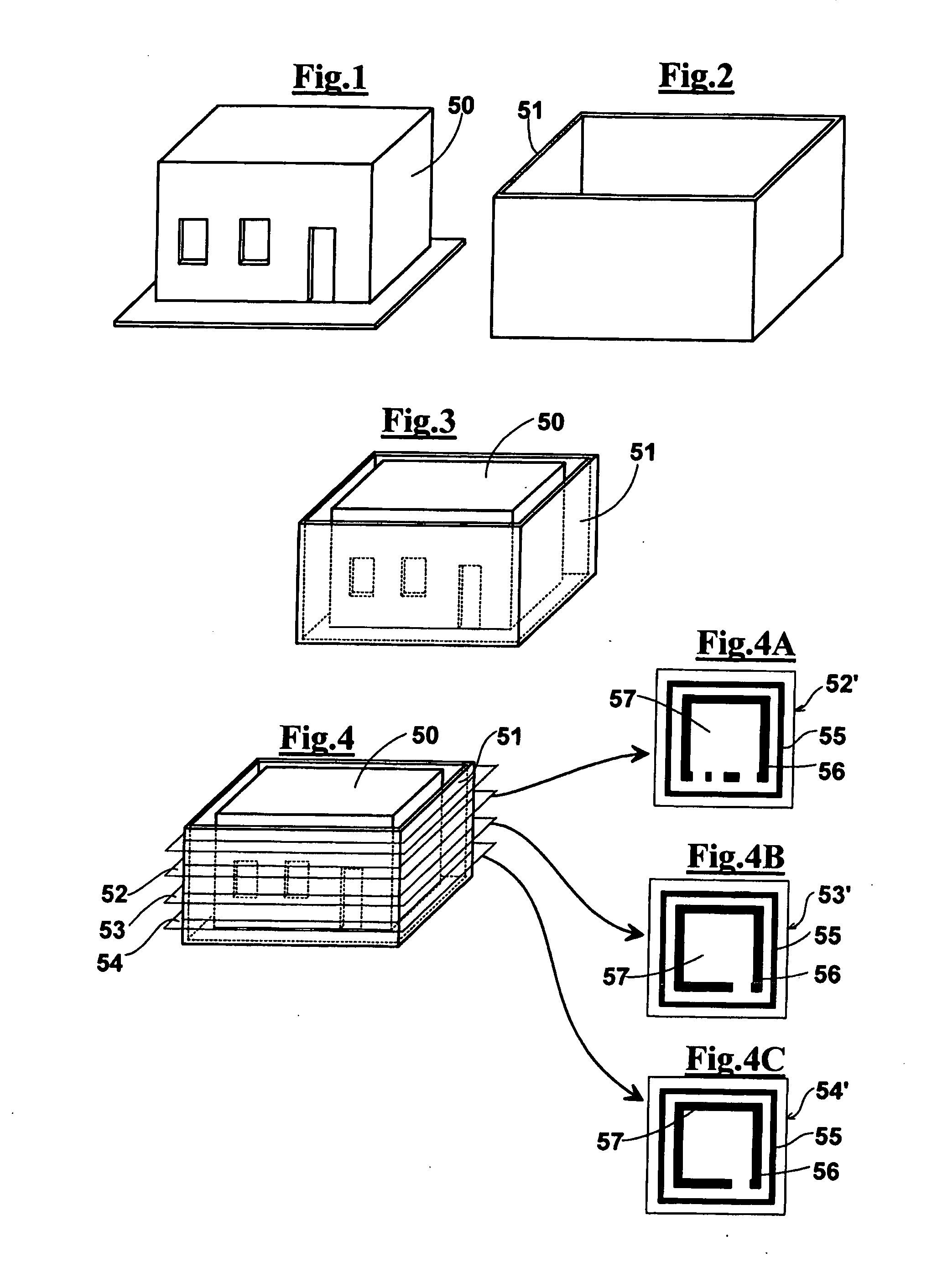
[0120]As shown in FIGS. 1 to 4, a method for automatically building conglomerate structures provides a first step of computer aided modelling operation of a building or other masonry construction structure 50 by a solid modelling CAD software, creating a file which contains a model of the structure 1 to be erected. Besides the model of the structure 50, the present method provides a computer aided modelling of a containing shell 51, (FIG. 2), which surrounds the model of the structure 50, as shown in FIG. 3. The model of this shell 2 provides an open upper side, and has preferably vertical walls, for example four vertical walls, such that it looks like a box containing the structure to be erected. The model of the containing spell 51 can be manually drawn about the model of the structure 50, or automatically drawn by a preset function of the program; in particular, the containing shell is spaced at a prefixed distance from the building.

[0121]The following step of the method consists...


PUM

PropertyMeasurementUnit
Lengthaaaaaaaaaa
Lengthaaaaaaaaaa
Force constantaaaaaaaaaa

Abstract

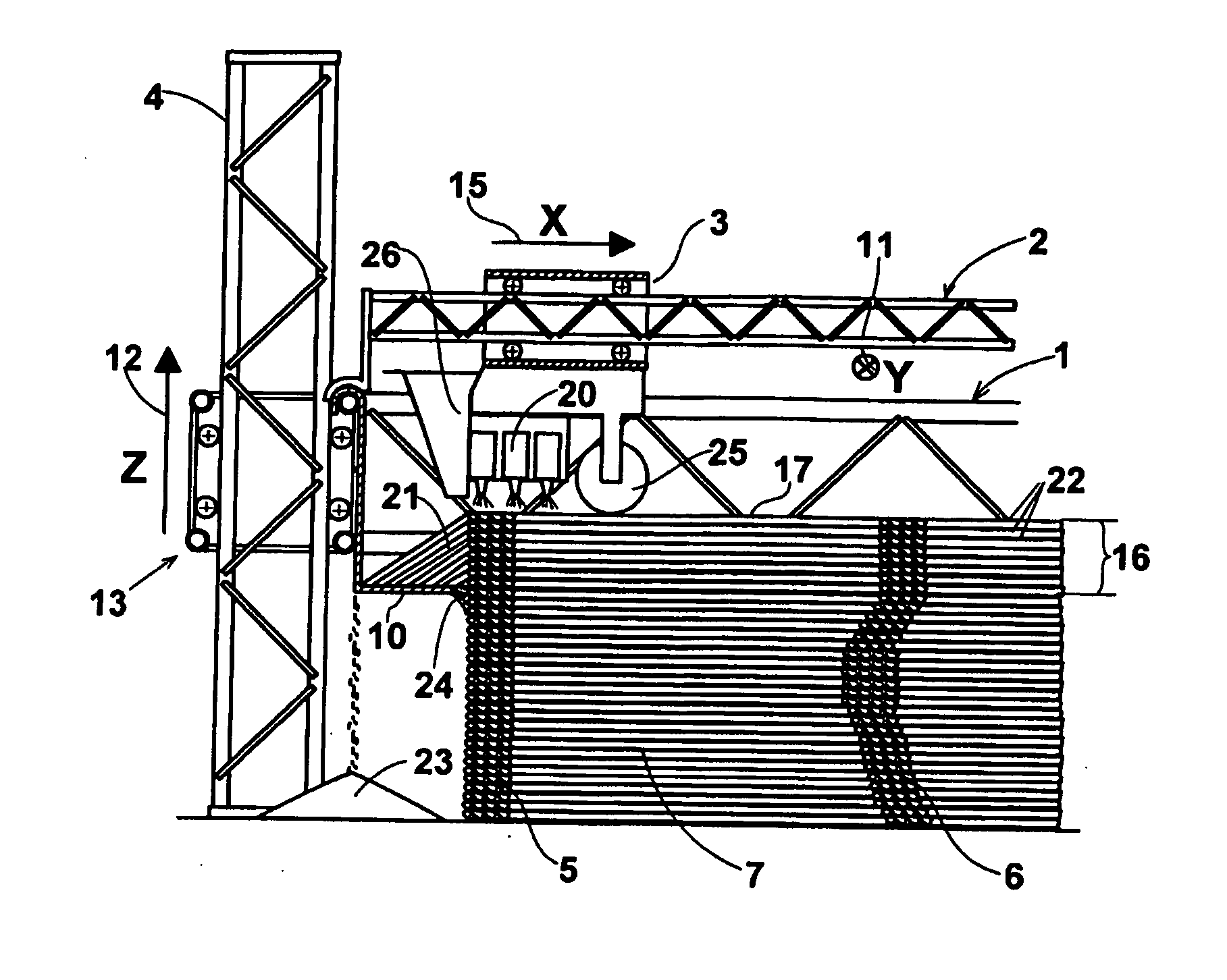
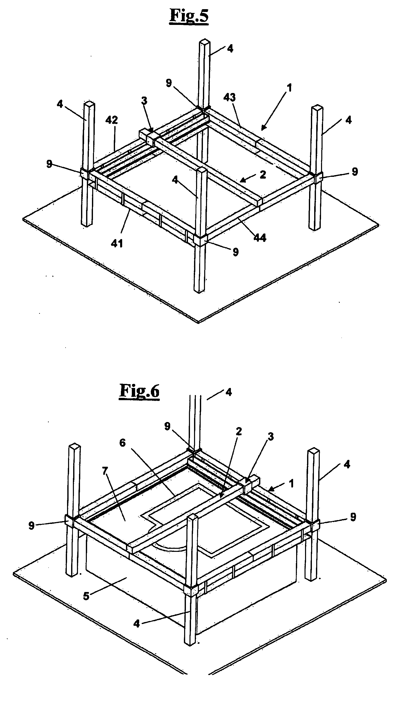
A method and an apparatus for automatically making conglomerated structures (6). The method comprises a) modelling a building structure and a containing shell about the structure by a computer using a CAD software thus obtaining a file; b) extracting sections of modelled structure and of modelled containing shell, by means of horizontal planes spaced apart of a predetermined pitch, such that a plurality of section planes is generated, said planes being sorted from below towards above with respect to the model of the structure and of the model of the shell; c) depositing by a moving unit (3) on a ground a bottom-to-top plurality of layers of granular material (22) alternate to a binding material liquid sprayed on the layers at filled areas corresponding to filled portions of the of the structure and of the containing shell, according to a predetermined path; d) vertically raising the moving unit (3) according to a pitch between a deposited layer and the following layer; e) repeating the step of depositing granulating material and repeating the step of spraying the binding material on a granulated material at filled areas of the structure and of the shell as many times as the planar cross sections into which said structure and the containing shell have been divided, each of said times for a different and consecutive section plane until the last layer (17) is complete; f) demolishing the containing shell (5) and removing unbound granular material (7) accumulated in the shell (5), thus releasing a conglomerate structure (6) that reproduces accurately said modelled structure. The apparatus comprises a horizontal frame (1), a bridge (2) sliding on guide on the horizontal frame (1), a moving unit (3) sliding along the bridge (2) or integral to the bridge (29) and have a spraying head (20). The horizontal frame (1) is moved along uprights (4) by a step actuator. The apparatus comprises a plurality of “skirts” (10) that surround the containing shell (5) and are integral to the horizontal frame (1). Such skirts scrape the outer surface of the containing shell (5) collecting the granular material (21) deposited out of the shell (5). Such skirts (10) can comprise an brush-like edge (20) suitable for externally sweeping the containing shell (5).

Description

FIELD OF THE INVENTION[0001]The present invention relates to the field of the building industry and more precisely it relates to a method for automatically making building structures and other masonry constructions, in particular for structures having stone-like physical and mechanical properties.[0002]Furthermore, the invention relates to an apparatus suitable for carrying out the method.BACKGROUND OF THE INVENTION[0003]A well-known method for automatically constructing conglomerate structures, in particular buildings, is described in patent application PI2005A000031. The method is carried out by a computer-aided apparatus, described in the same document, having a portion which can be moved according to the directions of three axes, one of which is vertical; this apparatus is suitable for laying alternate layers of inert granular material and a liquid binding material, in particular an epoxy resin or a polyurethane resin, creating a stone-like regions in predetermined points of a l...

Claims


Application Information

Patent Timeline
IPC IPC(8): E04G11/22G06F17/50E04B1/16
CPCB28B1/001B28B7/465E04B1/3505B29C67/243E04B1/161B29C67/0081B29C64/165B33Y80/00B33Y10/00B33Y70/10
Inventor DINI, ENRICO
Owner DINI ENRICO
Learn More