Digital camera and digital camera system
a digital camera and camera system technology, applied in the field of digital cameras and digital camera systems, can solve the problems of spurious resolution or false image structure, it is difficult to distinguish such color artifacts from actual present color, and it is difficult to distinguish false image structure from actual image structure based on interpolation algorithm, etc., to achieve the effect of reducing spurious resolution and high image quality
- Summary
- Abstract
- Description
- Claims
- Application Information
AI Technical Summary
Benefits of technology
Problems solved by technology
Method used
Image
Examples
first embodiment
[0165]FIG. 26 shows the configuration of a camera system 100 achieved in the first embodiment. The camera system 100 includes a digital camera (electronic camera) 1 and a personal computer 10. The digital camera 1 comprises a photographic lens 2, an optical low pass filter 3, an image sensor 4, an image processing unit 5 and a control unit 6.
[0166]The digital camera 1 is a single lens reflex digital camera and the photographic lens 2 is an exchangeable lens. The photographic lens is mounted at the digital camera 1 via a lens mount unit (not shown). The group of exchangeable lenses that can be mounted at the digital camera 1 is a group of exchangeable lenses compatible with both the digital camera and film cameras in the related art. The photographic lens 2 includes an aperture 7 equipped with an aperture mechanism capable of aperture control to adjust the aperture number within a range between the maximum aperture number (at least F2.8 or a smaller F number) and F8 or a greater F nu...
second embodiment
[0266]Optical low pass filters that may be used in the digital camera in the second embodiment adopt a structure different from that in the first embodiment. Since other structural features are identical to those in the first embodiment, a repeated explanation is not provided. The following is a description of the optical low pass filters achieved in the second embodiment.
[0267](Optical Low Pass Filter Structure)
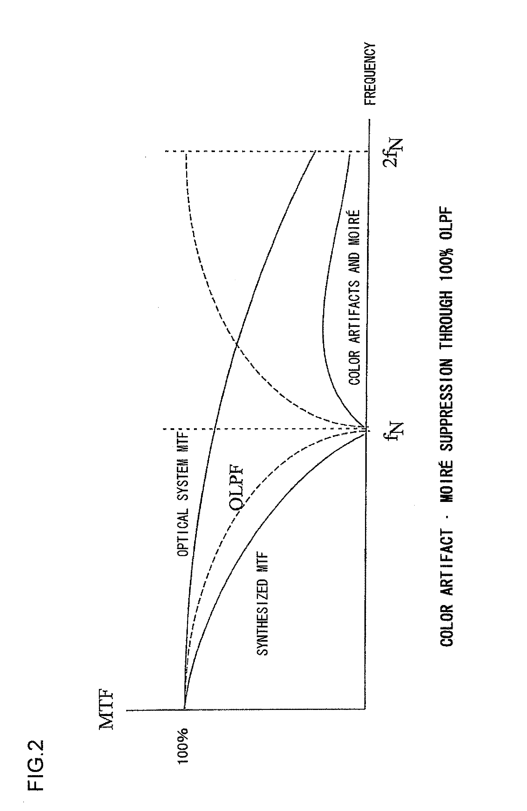
[0268]In the second embodiment, the vertical unidirectional structure equipped with a single birefringence plate, which does not achieve symmetrical filtering but assures outstanding definition, among the three types of optical low pass filters described earlier, is adopted. Such an optical low pass filter with a simpler structure will contribute to cost reduction. By determining the strength at which a color moiré•spurious resolution-free state is achieved at F2.8, as indicated in FIG. 15 in reference to which that geometrical optics simulation has been described earlier, s...
third embodiment
[0277]The digital camera in the third embodiment is equipped with an optical low pass filter adopting a structure different from that in the first embodiment. Since other structural features are identical to those in the first embodiment, a repeated explanation is not provided. The following is a description of the optical low pass filters achieved in the third embodiment.
[0278](Optical Low Pass Filter Structure)
[0279]In the third embodiment, the vertical / horizontal bidirectional structure equipped with two symmetrical birefringence plates, among the three different types of optical low pass filters described earlier, is adopted. As has been described in the earlier section on the geometrical optics simulation, the results of the investigation conducted under the various lens utilization conditions indicated in FIGS. 13, 16 and 17 to determine which of the two types of optical low pass filters, i.e., the vertical / horizontal bidirectional type and the diagonal bidirectional type, wou...
PUM
 Abstract
Description
Claims
Application Information
 - R&D
- Intellectual Property
- Life Sciences
- Materials
- Tech Scout
- Unparalleled Data Quality
- Higher Quality Content
- 60% Fewer Hallucinations
Browse by: Latest US Patents, China's latest patents, Technical Efficacy Thesaurus, Application Domain, Technology Topic, Popular Technical Reports.
© 2025 PatSnap. All rights reserved.Legal|Privacy policy|Modern Slavery Act Transparency Statement|Sitemap|About US| Contact US: help@patsnap.com


