Exhaust gas purifying system
Active Publication Date: 2010-08-12
NISSAN MOTOR CO LTD
View PDF14 Cites 14 Cited by
- Summary
- Abstract
- Description
- Claims
- Application Information
AI Technical Summary
Benefits of technology
[0008]In the conventional methods as described above, it is difficult to ensure compatibility between reduction of nitrogen oxide and oxidation of hydrocarbons. Therefore, lowering fuel efficiency and requiring a large amount of catalyst storage and quantity is unavoidable in order to purify the exhaust gas.
[0009]The present invention has been made focusing on the above-mentioned conventional problems. An object of the present invention is to provide an exhaust gas purifying system capable of achieving compact catalyst systems and ensuring compatibility between reduction of nitrogen oxide and oxidation of hydrocarbons.
[0010]The first aspect of the present invention provides an exhaust gas purifying system for an internal combustion engine, the system including: a NOx trapping agent which adsorbs nitrogen oxide when an excess air ratio of exhaust gas is more than 1, and releases nitrogen oxide when the excess air ratio is 1 or less; a NOx purifying catalyst which reduces nitrogen oxide to nitrogen; and an oxygen concentration controller which controls oxygen concentration in the exhaust gas, wherein, when the excess air ratio of the exhaust gas is more than 1, nitrogen oxide is adsorbed to the NOx trapping agent, and when the excess air rati
Problems solved by technology
In the conventional methods as described above, it is difficult to ensure compatibility between reduction of nitrogen oxide and oxidation of hydrocarbo
Method used
View moreImage
Smart ImageViewing Examples
Examples
 PUM
 Abstract
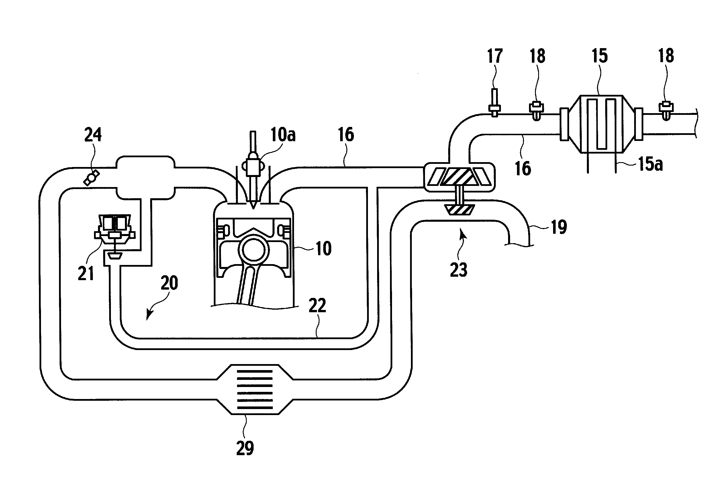
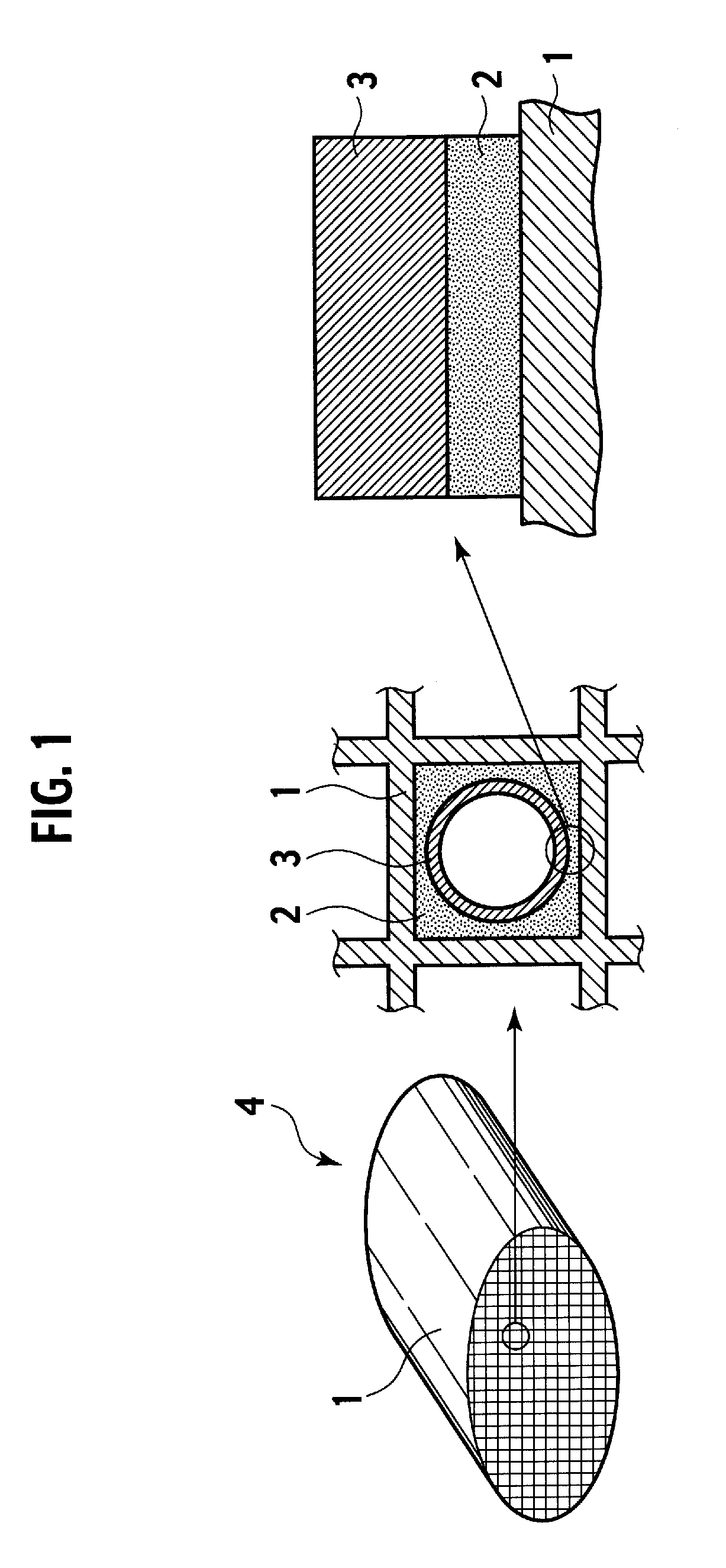
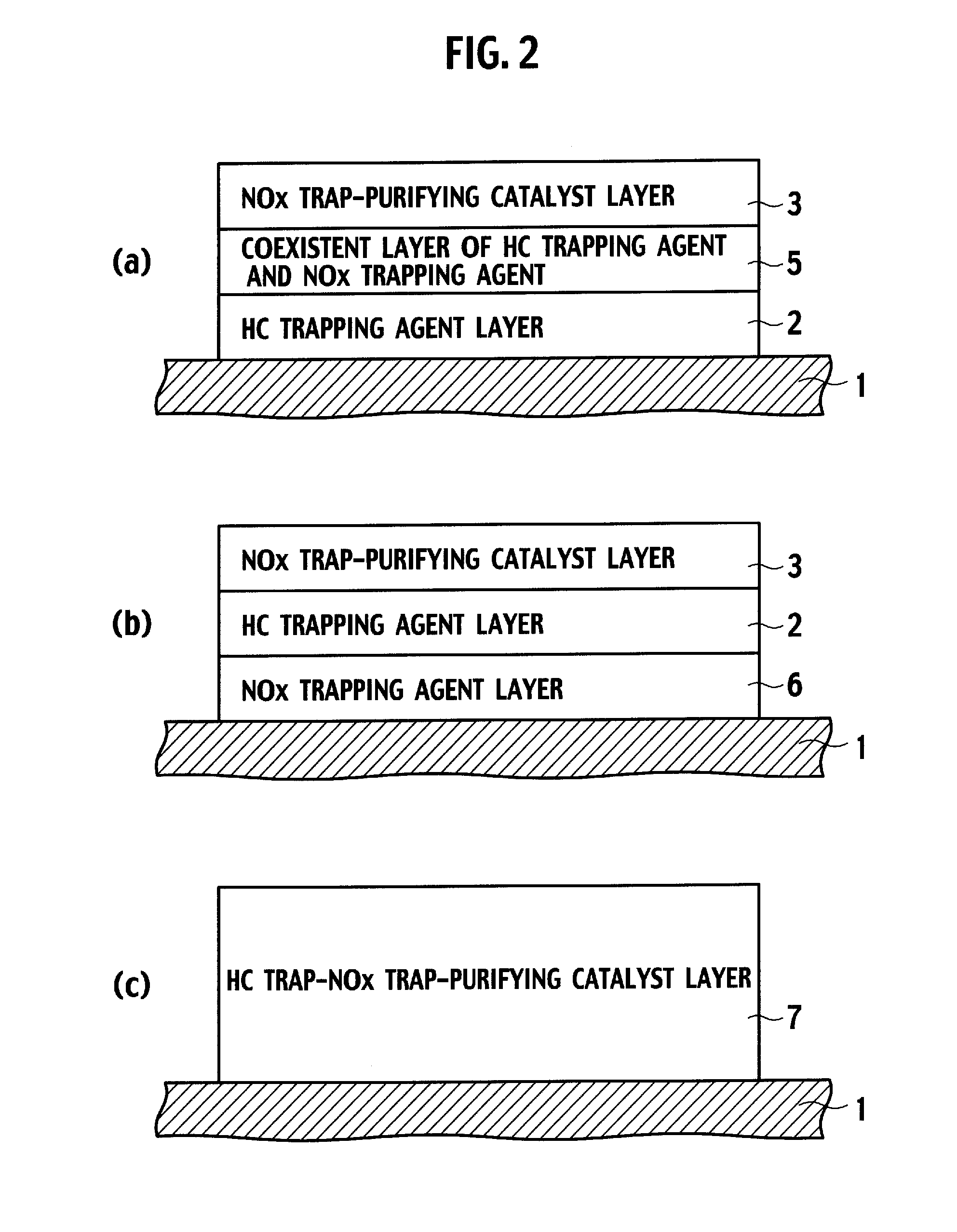
An exhaust gas purifying system includes: a NOx trapping agent (2) which adsorbs nitrogen oxide when an excess air ratio of exhaust gas is more than 1, and releases nitrogen oxide when the excess air ratio is 1 or less; a NOx purifying catalyst (13) which reduces nitrogen oxide to nitrogen; and an oxygen concentration controller which controls oxygen concentration in the exhaust gas. When the excess air ratio of the exhaust gas is more than 1, nitrogen oxide is adsorbed to the NOx trapping agent (2). When the excess air ratio of the exhaust gas is 1 or less, the oxygen concentration controller controls the oxygen concentration of the exhaust gas at an inlet of the NOx purifying catalyst between 0.8 and 1.5% by volume, so that the NOx purifying catalyst reduces nitrogen oxide released from the NOx trapping agent.
Description
TECHNICAL FIELD[0001]The present invention relates to an exhaust gas purifying system which purifies an exhaust gas discharged from an internal combustion engine. Particularly, the present invention relates to an exhaust gas purifying system capable of effectively purifying an exhaust gas discharged from an internal combustion engine during lean burn operation.BACKGROUND ART[0002]In recent years, since a demand to reduce carbon dioxide (CO2) emissions is increasing for global environmental concern, lean-burn operation has been aimed to improve fuel efficiency of an internal combustion engine for a vehicle. Meanwhile, nitrogen oxide (NOx) cannot be substantially reduced by conventional three-way catalysts because exhaust gas from lean burn engines using gasoline, direct-injection engines and diesel engines contains a lot of oxygen because of lean combustion. Now, diverse technological developments have been enhanced to efficiently purify the exhaust gas from engines, especially from ...
Claims
Login to View More Application Information
Patent Timeline
 IPC IPC(8): F01N9/00F01N3/10F01N3/20F01N11/00F02M25/07
CPCF01N3/0814F01N3/0871F01N2240/16F01N13/009F01N2510/0682Y02T10/24F01N2510/063F01N3/0807F01N3/0835F01N3/0842F01N3/2013F01N9/00F01N11/007F01N2370/04F01N2430/06F01N2510/06F01N2560/023F01N2560/026F01N2570/12F01N2570/14F02D41/0275F02D2200/0806Y02T10/12Y02T10/40Y02A50/20F01N3/18
Inventor AKAMA, HIROSHIONODERA, HITOSHI
Owner NISSAN MOTOR CO LTD
Features
- R&D
- Intellectual Property
- Life Sciences
- Materials
- Tech Scout
- Unparalleled Data Quality
- Higher Quality Content
- 60% Fewer Hallucinations
Learn More Browse by: Latest US Patents, China's latest patents, Technical Efficacy Thesaurus, Application Domain, Technology Topic, Popular Technical Reports.
© 2025 PatSnap. All rights reserved.Legal|Privacy policy|Modern Slavery Act Transparency Statement|Sitemap|About US| Contact US: help@patsnap.com


