
Sprinkler

Active Publication Date: 2010-08-05
YUAN MEI CORP
View PDF4 Cites 12 Cited by
  • Summary
  • Abstract
  • Description
  • Claims
  • Application Information

AI Technical Summary

Benefits of technology

[0006]Aspects of the invention overcome deficiencies of prior technologies by providing an interconnected channel within the sprinkler head. Aspects of the invention provide an improved sprinkler that uses a movable piece which includes a gear chamber and a control chamber. A set of dividers or dividing plates or blades (an upper blade and a lower blade) separates the gear chamber and the control chamber. The separation forms or results a water filtering space to direct water to flow from the control chamber and prevent water with debris to enter the gear chamber. As such, the water from the control chamber can be filtered in the water filtering space, filtering out water with debris, before it enters the gear chamber. Thus, aspects of the invention not only provide lubrication and cooling from water to the gear set during its operations, but also protect the gear set by preventing an accumulation of debris. Aspects of the invention also ensure the smooth operations of the gear set and maintain a balanced water temperature and pressure between the gear chamber and the control chamber and achieve an optimal balance of the temperature and pressure.
[0007]Alternative aspects of the invention provide a gear set that is completely or substantially completely enclosed within the interior of the gear chamber of movable piece and can mesh with the blade of the main gear and the stationary gear of the inlet pipe. Such design ensures the complete protection of the gear chamber, prevents external interferences and prevents unexpected seepage of water from the gear chamber, and maintains the optimal usage condition of the sprinkler.
[0008]According to another aspect, an improved sprinkler includes a water switching device to change a water flow direction to control a blade and a direction of a gear set to oscillate a movable set. The sprinkler includes a set of an upper divider and a lower divider positioned within an interior of the movable set and dividing the interior of the movable set into a water control chamber and a gear chamber. The water control chamber includes a water switching device therein, and the gear chamber includes a gear set therein. The movable set includes a bottom end, and the bottom end of the movable set includes a connecting pipe with a stationary gear section. The stationary gear section meets with a gear within the gear set. The gear set is substantially or completely enclosed in the gear chamber, and the water flowing inside the connecting pipe is accessible to the control chamber only to direct water to the control chamber. The upper divider and the lower divider comprise a set of matching ribs and receiving grooves that form a water filtering space to enable the water from the control chamber to flow through the filtering space before seeping through the gear chamber while filtering out larger particles in the water and assisting in cooling and lubrication of the gear set. In another aspect, the As such, aspects of the invention further prevent frictional damages between gears in the gear set and to maintain the water pressure and temperature differences between water in the control chamber and the gear chamber.

Problems solved by technology

After an extended use, debris of various sizes in the water enters the sprinkler without any filtering, and cause damages to the gears inside the interior of the sprinkler.
Consequently, the operation of the sprinkler is interfered and the usage life of the sprinkler is reduced.
Similarly, other kinds of sprinkler describe a divided interior, but during operations, each gear may easily damaged when friction among the gears increases when the lubrication and cooling from the water decreases.
This phenomenon further leads to a lack of balance between the water pressure and temperature in the gear chamber.
As such, they are easily affected negatively by external forces and the gears' operations will also be negatively affected.
This further prevents the gear chamber get proper lubrication and cooling from the water.
In addition, even if lubricant were added in the gear chamber, the lubricant will still slowly leak from the blade in the un-enclosed gear chamber.
Thus, eventually, the lubricant will be lost and the purpose of lubrication of the gear chamber using the lubricant will be lost as well.

Method used


Image

  • Sprinkler
  • Sprinkler
  • Sprinkler

Examples


Embodiment Construction

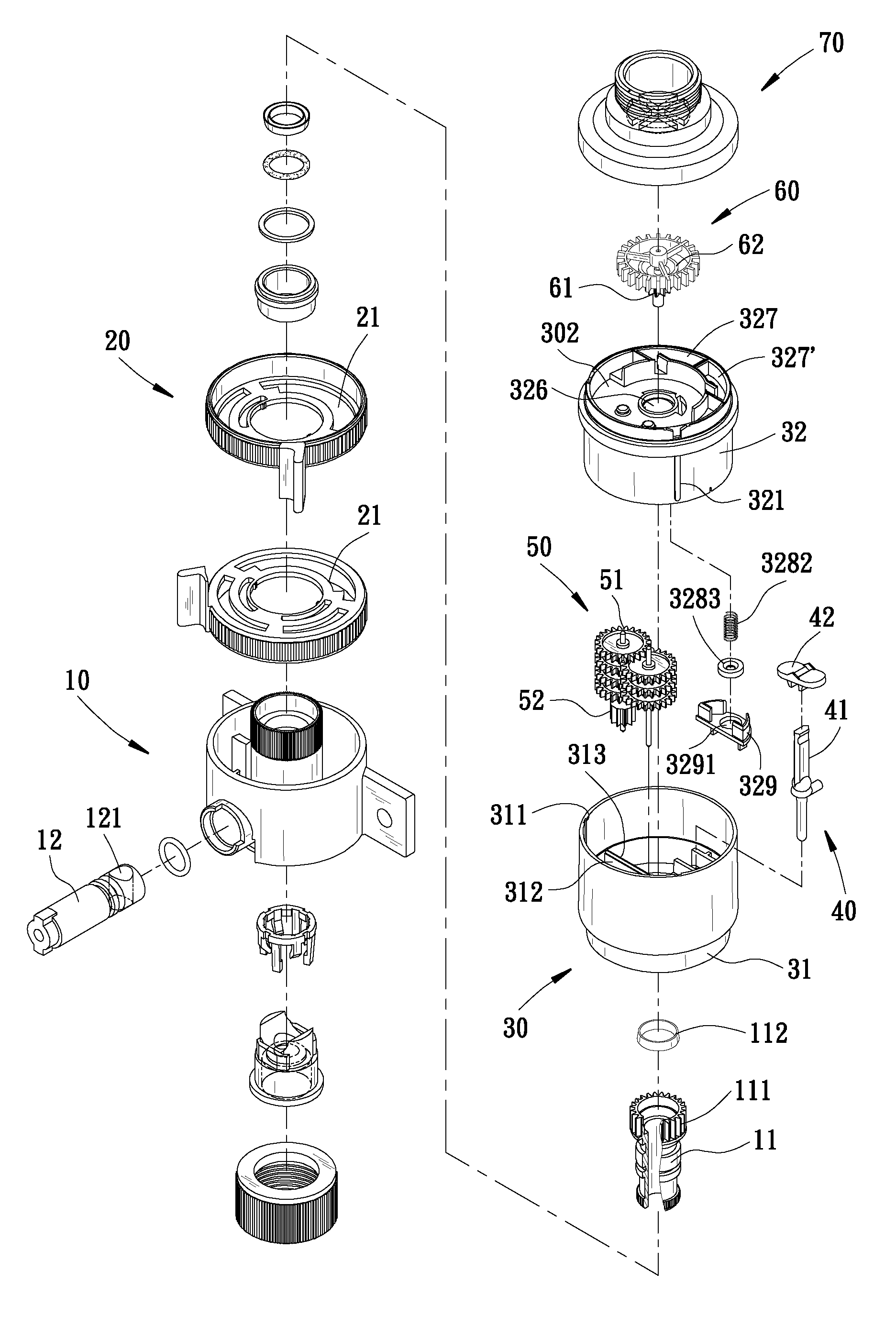
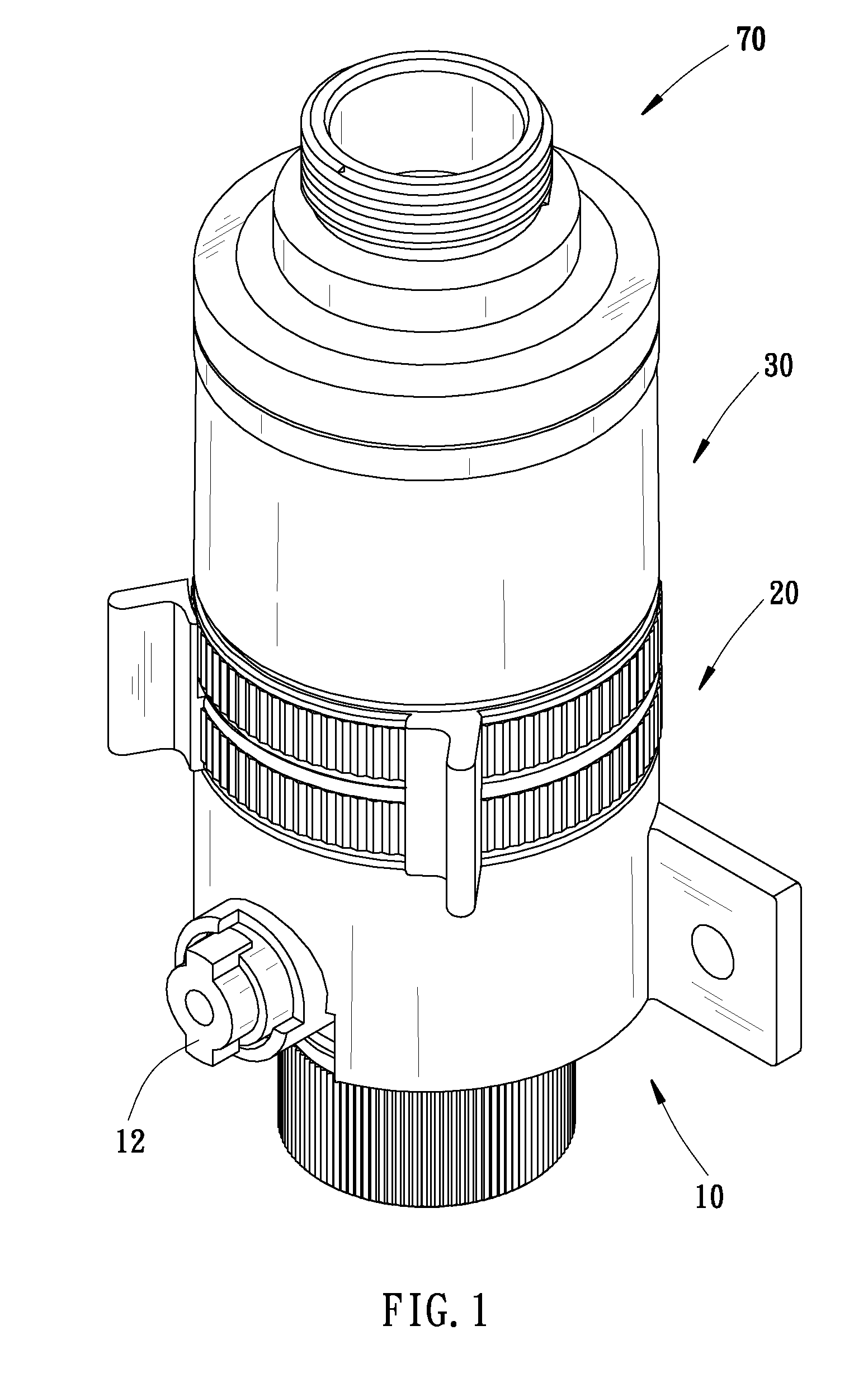
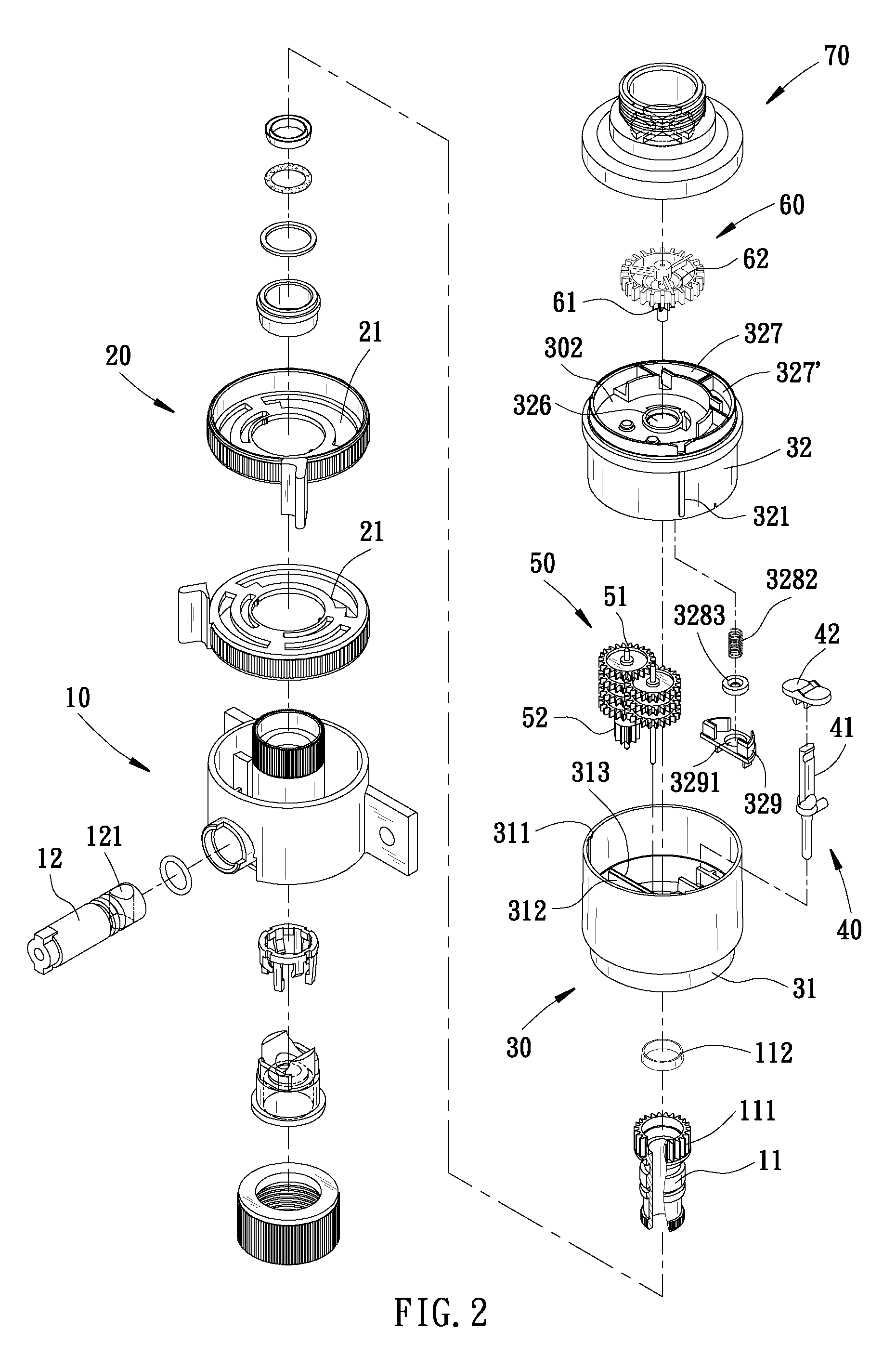
[0025]The following list shows reference characters used through FIGS. 1-12:[0026]10—a water inlet;[0027]11—a connecting pipe;[0028]111—a stationary gear;[0029]112—a restricting o-ring;[0030]12—an adjustable valve;[0031]121—an adjustable opening;[0032]20—a restricting connector;[0033]21—a restricting space;[0034]30—a movable set;[0035]301—a restricting handle;[0036]302—a collecting space;[0037]31—an end box;[0038]311—wall groove;[0039]312—a lower divider;[0040]313—a first rib;[0041]314—a first section;[0042]315—a second section;[0043]316—a hole;[0044]317—a small diameter chamber;[0045]32—a cover;[0046]321—a second rib;[0047]322—an upper divider;[0048]323—a receiving groove;[0049]324, 324′—openings;[0050]325—a semi-circle space;[0051]326—an opening;[0052]327—a first duct;[0053]327′—a second duct;[0054]328—a water outlet space;[0055]3281—a rod;[0056]3282—a spring;[0057]3283—a washer;[0058]329—a release cover;[0059]3291—a pressure release opening;[0060]33—a control chamber;[0061]34—a g...


PUM


Abstract

An improved sprinkler has a flow altering device to change water direction and control the direction of a blade wheel. A gear set causes a sprinkler head's repetitive rotation. The sprinkler head includes a set of corresponding upper plate and lower plate to divide an interior chamber of the sprinkler head to two chambers: a control chamber and a gear chamber. A water inlet pipe connects only with the control chamber to provide water to enter the control chamber. The upper plate and the lower plate form a filtering channel interconnecting between the control chamber and the gear chamber. The water from the control chamber can flow into the gear chamber through the filtering channel. The filtering channel filters the large / coarser particle debris in the water and the water flowing into the gear chamber can lubricate and cool the gear set in the gear chamber.

Description

BACKGROUND OF THE INVENTION[0001]1. Field of the Invention[0002]Embodiments of the invention generally relate to an improvement on sprinkler head structure. In particular, aspects of the invention relate to a multi-chambered interior of the sprinkler head to alleviate damages thereto due to debris contained in water.[0003]2. Background of the Invention[0004]In one previously known technology, a common sprinkler includes an inlet pipe having water flowing into the interior of the sprinkler before the water exits from the nozzle of the sprinkler. After an extended use, debris of various sizes in the water enters the sprinkler without any filtering, and cause damages to the gears inside the interior of the sprinkler. Consequently, the operation of the sprinkler is interfered and the usage life of the sprinkler is reduced.[0005]Similarly, other kinds of sprinkler describe a divided interior, but during operations, each gear may easily damaged when friction among the gears increases when...

Claims


Application Information

Patent Timeline
IPC IPC(8): B05B3/04
CPCB05B1/3026B05B3/001B05B15/02B05B3/0436B05B15/008B05B3/0431B05B15/50B05B15/40
Inventor LO, SHUN NAN
Owner YUAN MEI CORP
Learn More