
Laser cutting process for forming stents

Active Publication Date: 2010-08-05
ABBOTT CARDIOVASCULAR
View PDF88 Cites 29 Cited by
  • Summary
  • Abstract
  • Description
  • Claims
  • Application Information

AI Technical Summary

Benefits of technology

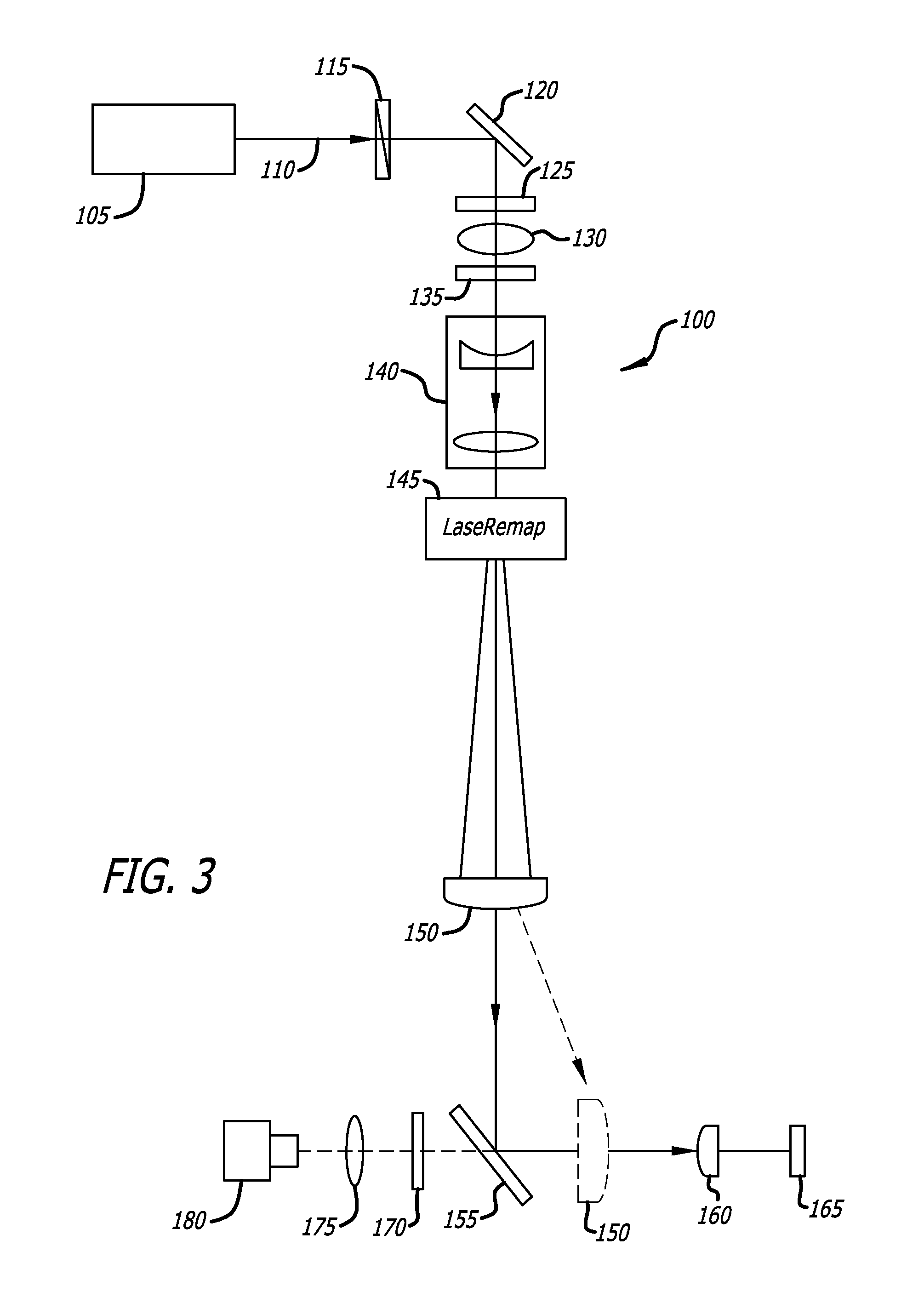
[0022]In one aspect, the present invention is embodied in a system that utilizes a laser beam that has been shaped using a shaping module to modify the intensity profile of the laser beam. In other aspects, the shaped laser beam has a more even intensity profile across the relevant beam diameter than is typically delivered by a non-shaped laser beam having a Gaussian profile. Control over such a shaped laser beam produces cleaner surfaces and faster fabrication times. Use of a shaped beam having an alternative energy profile may also result in improved stent characteristics that are advantageous to stent performance and function. For example, shaped laser beam profiles may result in a steeper stent sidewall than is obtainable using a laser beam with a Gaussian intensity distribution, which may improve manufacturability and performance of the stent. Moreover, use of shaped laser beams formed in accordance with the various aspects of the present invention may also result in improved stent cutting speeds, optical characteristics, and drug retention characteristics. It will be understood that the laser beam shaping technology described herein can be used for forming other medical device components, particularly where improved edge surfaces or component fits and the like are required. For example, such a system could be used to produce parts of a guidewire or catheter device. It may also be used to provide for precise machining of pacemaker components.
[0025]In still another aspect, the present invention provides a laser cutting process that enables greater control over the shape of the stent strut. The improved dimensional control is achieved in one aspect by offsetting the path of a laser beam from the central axis of a stent tube. By offsetting the laser from the central axis of the tube, the typical taper resulting from use of a Gaussian laser beam may be virtually eliminated, producing a stent strut with a much more rectangular shape.
[0027]In yet another aspect, a single laser beam can be used to cut both sides of a stent strut to result in a rectangular strut. The laser beam is moved from a first position having a first offset angle to a second position having a second offset angle so that the walls of each stent strut may be cut by the laser. In an alternative aspect, the stent tubing may be moved relative to the laser to accomplish the same result. In still another aspect, both the laser and the tube may be moved simultaneously to one another to achieve the same effect.

Problems solved by technology

Although the stents are effective in opening the stenotic lumen, the foreign material and structure of the stents themselves may exacerbate the occurrence of restenosis or thrombosis.
Although PTCA and related procedures aid in alleviating intraluminal constrictions, such constrictions or blockages reoccur in many cases.
This results in a tapered cut when the laser beam cuts through a material.
When a laser having a Gaussian intensity distribution is used to cut a stent strut the resulting tapered edge causes difficulty in achieving overall dimensional stability after electrochemical polishing.
The tapered edge shape may also not be ideal in carrying out its function when the stent is implanted in a vessel, as the tapered strut may not be ideal in opposing the vessel wall.
An additional problem with prior art systems that typically have used lasers that generate long laser pulses with durations in the microsecond range is that this type of laser removes material using a mostly thermal process, with some degree of evaporation of tubing material.
The thermal process of the long pulse laser may also result in production of a heat-affected zone in the stent tubing material.
This heat-affected zone, which occurs frequently when the stent tube is cut by the long pulse laser in the presence of certain reactive gases such as oxygen can result in embrittlement of the stent material and thus decreases mechanical performance of the stent material.

Method used


Image

  • Laser cutting process for forming stents
  • Laser cutting process for forming stents
  • Laser cutting process for forming stents

Examples


Embodiment Construction

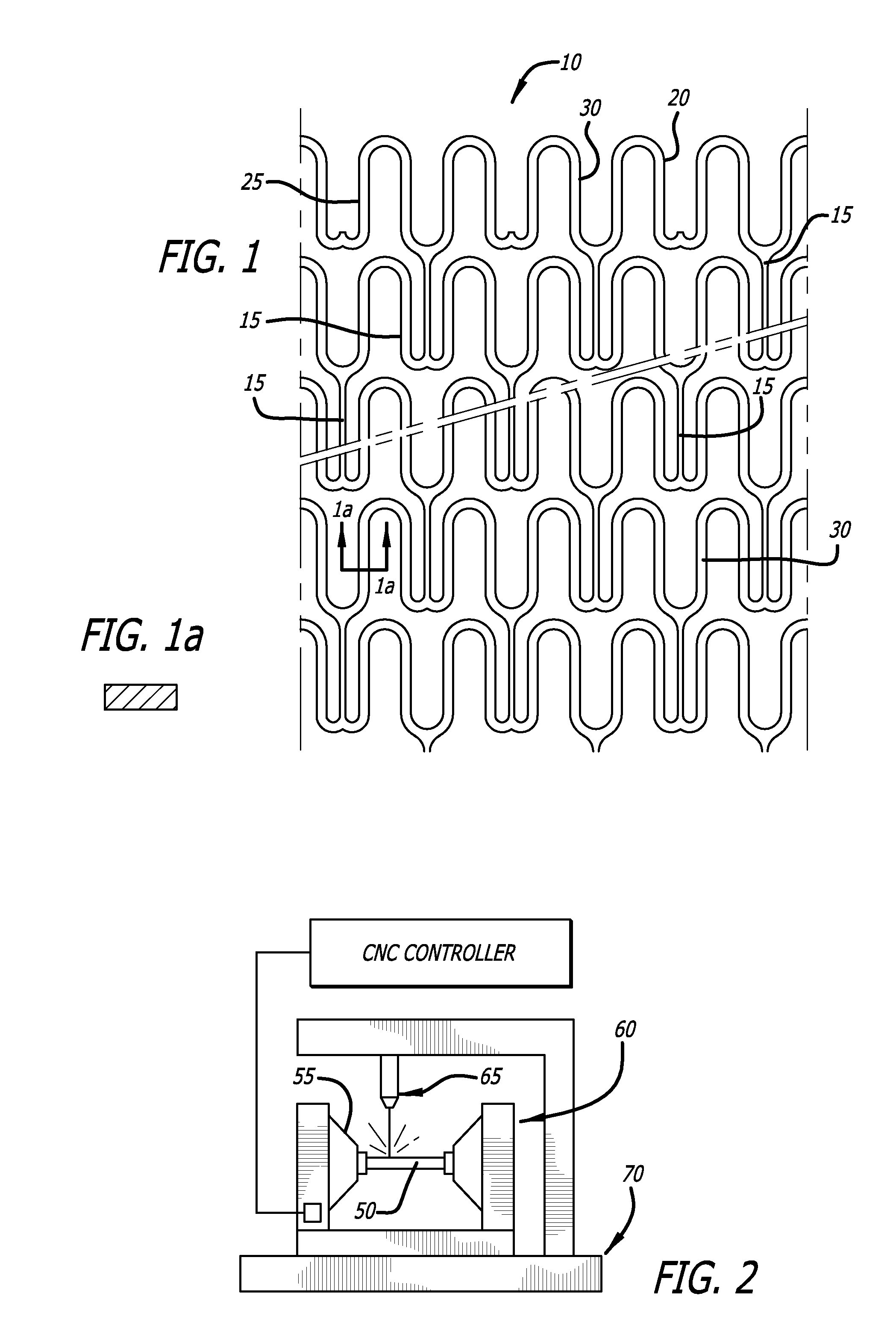
[0063]FIG. 1 is an enlarged perspective view of a stent 10 illustrating an exemplary stent pattern and showing the placement of interconnecting elements 15 between adjacent radially expandable cylindrical elements. Each pair of the interconnecting elements 15 on one side of a cylindrical element are preferably placed to achieve maximum flexibility for a stent. In the embodiment shown in FIG. 1, the stent 10 has three interconnecting elements 15 between adjacent radially expandable cylindrical elements which are 120 degrees apart. Each pair of interconnecting elements 15 on one side of a cylindrical element are offset radially 60 degrees from the pair on the other side of the cylindrical element. The alternation of the interconnecting elements results in a stent which is longitudinally flexible in essentially all directions. Various configurations for the placement of interconnecting elements are possible. However, as previously mentioned, all of the interconnecting elements of an in...


PUM

PropertyMeasurementUnit
Thicknessaaaaaaaaaa
Distributionaaaaaaaaaa

Abstract

Systems and methods for improving the cutting efficiency and cut profile of stent strut is provided. A means for altering the energy distribution of a laser beam is provided, along with various ways of controlling a laser to provide for improved strut configurations are provided. A method for improved cutting speeds using a combination of laser sources is also provided.

Description

CROSS-REFERENCES TO RELATED APPLICATIONS[0001]This application claims priority from U.S. Provisional Application No. 61 / 149,630, filed Feb. 3, 2009 and U.S. Provisional Application No. 61 / 149,664, filed Feb. 3, 2009 and U.S. Provisional Application No. 61 / 149,667, filed Feb. 3, 2009 incorporated by reference in its entirety.[0002]This application is also related to U.S. application Ser. No. ______ entitled IMPROVED LASER CUTTING SYSTEM, filed Feb. 3, 2010, and U.S. application Ser. No. ______ entitled MULTIPLE BEAM LASER SYSTEM FOR FORMING STENTS, filed Feb. 3, 2010.BACKGROUND[0003]1. Field of the Invention[0004]The present invention relates generally to implantable medical devices and to a method for manufacturing implantable medical devices. These implantable medical devices may also be capable of retaining therapeutic materials and dispensing the therapeutic materials to a desired location of a patient's body. More particularly, the present invention relates to a method for formi...

Claims


Application Information

Patent Timeline
IPC IPC(8): B23K26/00
CPCA61F2/91B23K26/0626B23K26/0823B23K26/365A61F2240/001B23K26/36A61F2/915A61F2002/91566B23K26/38B23K26/361
Inventor CHEN, LIYRIBARREN, TRAVISVON OEPEN, RANDOLFKU, YU-CHUN
Owner ABBOTT CARDIOVASCULAR
Learn More