Multi deck aircraft

a multi-deck aircraft and fuselage shell technology, applied in aircraft floors, wing adjustments, air transportation, etc., can solve the problems of reducing the space beneath the lower deck, reducing the efficiency of multi-deck aircraft, and reducing the thickness weight, so as to maximize the freedom of passenger movement, increase the efficiency of multi-lobe aircraft, and minimize the thickness and weight of the fuselage shell.

Inactive Publication Date: 2010-07-29
MR MICHAEL YAVILEVICH
View PDF23 Cites 51 Cited by
  • Summary
  • Abstract
  • Description
  • Claims
  • Application Information

AI Technical Summary

Benefits of technology

[0009]In view of the above it is the aim of the invention to achieve the following embodiments and methods singly or in combination:a) to increase the passenger capacity of narrow and wide-body aircrafts in a such manner that passenger cabins or service facilities located in a lower deck can also be occupied by passengers and crew members during the take-off and landing phases of a flight and a sufficient standing height for passengers is achieved at in the lower deck, while simultaneously maintaining a functional freight loading system in the external cargo containers;b) to provide a raised portions in the upper deck floor of such an aircraft to form a passenger aisle in lower deck, having a sufficient standing height, while the lateral floor surface of the upper and lower decks is at a proper height to provide optional rows of seats arrangement;c) to elevate passenger seats regarding aisle floor in lower cabin of twin deck narrow and wide-body aircraft, to provide maximum width and distance from fuselage belly;d) to provide fuselage with tree-dimensional load-bearing inner cell structure included strengthened walls, thin stepped decks, ceilings and struts of upper and lower cabins and integrated with conventional semi-monocoque fuselage shell structure to maintain the integrity of the upper and lower lobes of aircraft fuselage in flight and in the event of an emergency landing;e) to provide fuselage airframe shell primary structure comprises several longitudinally spaced, vertically oriented main ring frames, beams and angle braces to transfer the load from the fuselage shell to wings of the aircraft and undercarriage mounting;f) to provide such an energy absorbing and safety unit that can be specifically tailored and installed on conventional aircraft having different configurations, to ensure energy absorption and protection in those areas of a lower deck to be occupied by passengers or service facilities.

Problems solved by technology

One problem with adding passenger seating, sleeping cabins or other passenger service facilities to cargo decks is that lower decks typically provide insufficient standing height.
Another problem with using lower, cargo decks for passengers is providing sufficient structure beneath the lower deck to protect passengers, in the event of a crash landing.
Lowering the floor of the lower deck as proposed by Schliwa compounds this problem because it further reduces the space beneath the lower deck.
The problem is even more serious if one considers the emergency evacuation of passengers, when aircraft digging on water, since big cargo doors in lower lobe decrease waterproof of conventional airliners.
The problem of dealing with terrorist bombs on board airlines has not been solved.
A plastic explosive device hidden inside checked luggage stored within Unit Load Devices (ULD) in a lower cargo hold can cause a rapid breakup of the aircraft.
Still another problem with using lower cargo decks for passengers is that aircraft fuel is typically carried in fuel vessels located within the central wing box of the aircraft which engage a big space in lower fuselage lobe.
There are accidents that were regrettably traced back to fires caused by kerosene leaking from an aircraft that had performed an emergency landing.

Method used


Image

  • Multi deck aircraft
  • Multi deck aircraft
  • Multi deck aircraft

Examples


Embodiment Construction

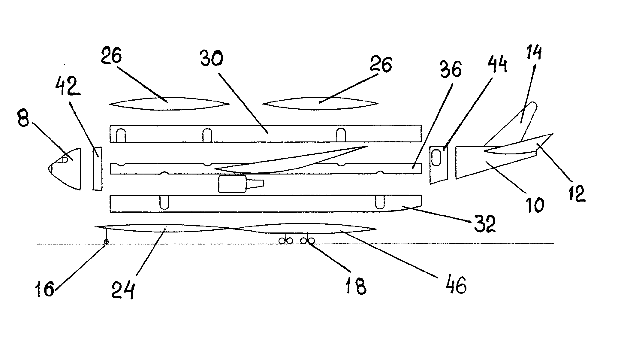
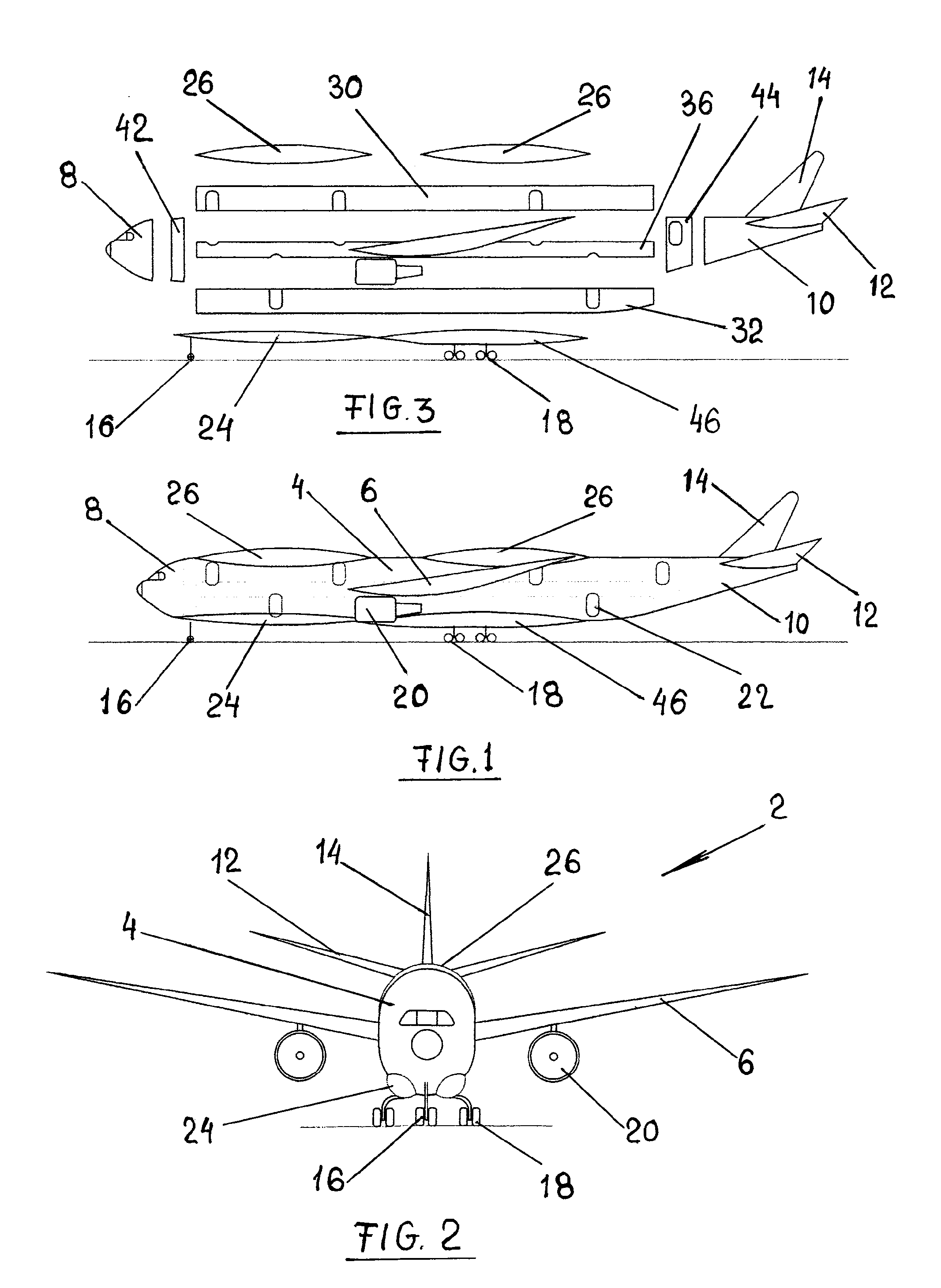
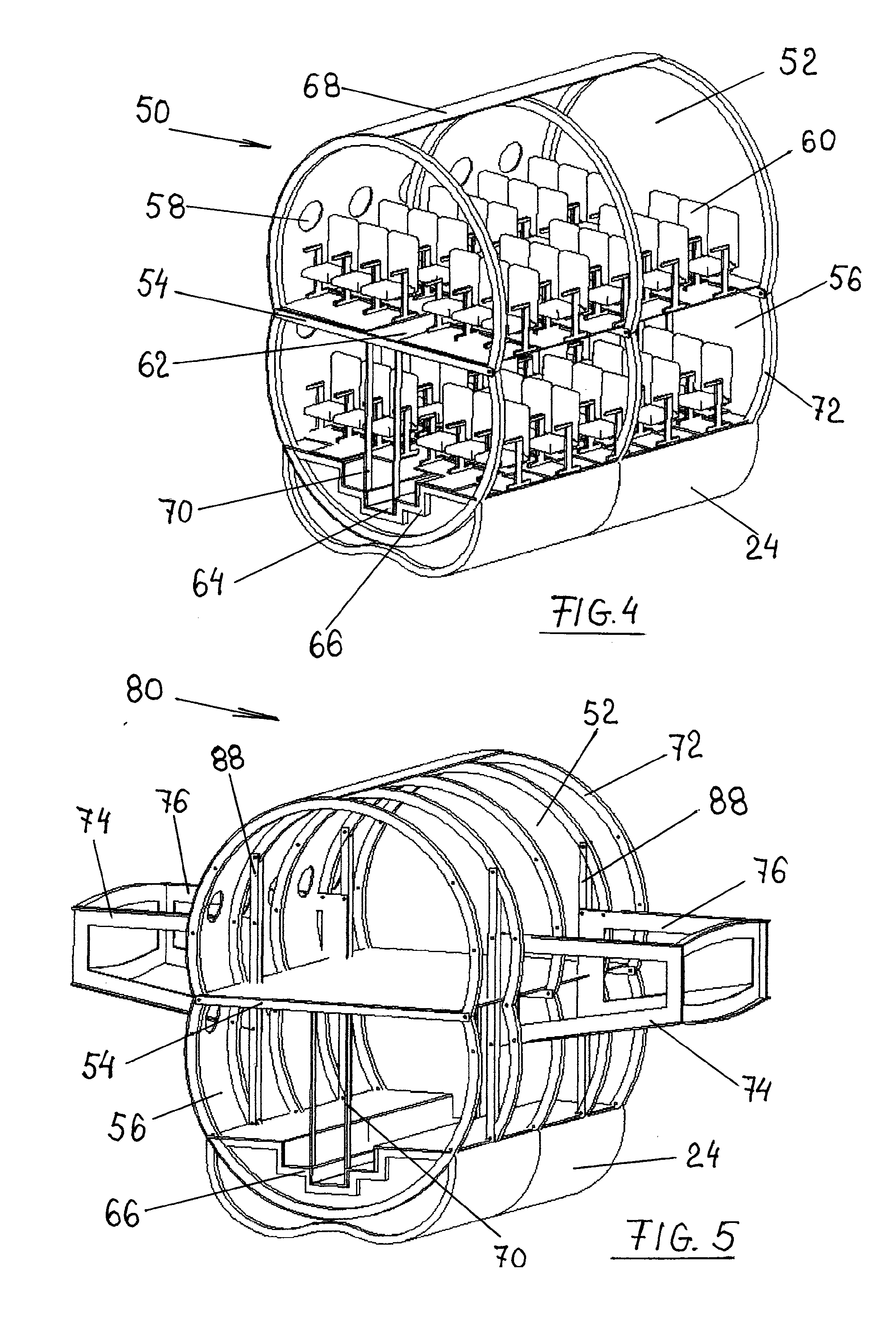
[0044]FIGS. 1 and 2 show side and front view of derivative twin deck aircraft 2. Aircraft 2 includes oval fuselage 4, wing 6, nose portion 8, tail portion 10 with horizontal 12 and vertical 14 stabilizers, forward landing gear 16, main landing gear 18 and turbofan engines 20 attached to the wing 6. Entrance and exit doors 22 and windows attached after redesign and assembling fuselage. Energy absorbing external cargo containers 24 attached to aircraft belly and external fuel tanks 26 positioned on a top of the fuselage 4, providing streamlined outer surface and increasing area-ruling drag reduction effect. The interchangeably external cargo containers 24 and auxiliary fuel tanks 26 have similar devices for connection with fuselage structure. The main landing gear 18 retracts in landing gear bays 46, shaped to have a streamlined outer contour with external containers 24. Detailed descriptions about passenger cabins show in FIGS. 4 and 8.

[0045]FIG. 3 shows exploded view of the method f...


PUM


Abstract

The invention relates to multi deck passenger aircraft, having passenger cabins and / or service facilities arranged on the upper and lower deck and inner load bearing cell structure provided within aircraft body. The present invention is also directed toward methods for manufacturing derivative multi deck aircrafts. Energy absorbing, floatable cargo containers (24) attached to fuselage belly. External fuel tanks (26) displaced on the top of fuselage. Center wing region of the fuselage is using for arranging rows of seats and service facilities. Addition seating configuration for narrow and wide bodied aircraft is provided. Multi deck seating configuration significantly reduces per passenger operating cost over existing technology. Less fuel per passenger is required since there is less airframe weight and wetted area per passenger. Due to the lower overall cost per passenger seat within the multi deck seating structure, the net profit and return on investment in the aircraft are also increased.

Description

TECHNICAL FIELD[0001]A present invention refers to methods and embodiments for increasing a seating capacity and an efficiency of passenger aircraft by manufacturing derivative multi deck airplanes.BACKGROUND ART[0002]One problem with adding passenger seating, sleeping cabins or other passenger service facilities to cargo decks is that lower decks typically provide insufficient standing height. One attempt to overcome this problem is disclosed in U.S. Pat. No. 5,752,673 assigned to Schliwa et al. This invention discloses lowering the floor in an aisle section of the lower deck to provide at least enough clearance for a standing person of normal height.[0003]Another problem with using lower, cargo decks for passengers is providing sufficient structure beneath the lower deck to protect passengers, in the event of a crash landing. Regulations could require at least 30 inches of compressible structure beneath the lower deck if the lower deck is to be used to carry passengers. Lowering t...

Claims


Application Information

Patent Timeline
IPC IPC(8): B64C3/00B64D11/06B64D47/00B64D37/04B64C1/22B64D45/00B64D13/02B64C1/06
CPCB64C1/061B64C1/062B64C2001/0027B64C2001/0036B64C2001/0072Y02T50/46B64D11/00B64D37/04Y02T50/433Y02T50/44B64D9/00Y02T50/40
Inventor YAVILEVICH, MICHAEL
Owner MR MICHAEL YAVILEVICH
Why Eureka
Try Eureka