
Test system combination for testing several systems under test in parallel, comprising several test systems

a test system and test system technology, applied in the field of test systems, can solve the problems of limited scalability and computing power, and the difficulty of joint testing of several different systems under test, and achieve the effect of reducing reaction tim

Active Publication Date: 2010-07-08
AIRBUS OPERATIONS GMBH
View PDF10 Cites 21 Cited by
  • Summary
  • Abstract
  • Description
  • Claims
  • Application Information

AI Technical Summary

Benefits of technology

The present invention is about an improved test system for aircraft that can test several systems simultaneously in parallel. The test system includes several individual test systems that can simulate different electrical environments of the systems under test. These test systems are connected to a master network, which allows for a centralized control and data exchange. The test system assembly features a workstation for controlling and configuring test sequences, as well as data memory for storing measuring data. The test system assembly can also have an online operating mode, in which the test systems simulate the original environment of the systems under test. The technical effects of the invention include improved efficiency and accuracy in testing aircraft systems and the ability to simulate complex scenarios.

Problems solved by technology

In addition, the scalability and the computing power may be limited.
Joint tests of several different systems under test frequently can only be carried out under more difficult conditions.

Method used


Image

  • Test system combination for testing several systems under test in parallel, comprising several test systems
  • Test system combination for testing several systems under test in parallel, comprising several test systems
  • Test system combination for testing several systems under test in parallel, comprising several test systems

Examples


Embodiment Construction

[0054]The figures show schematic illustrations that are not true-to-scale.

[0055]In the following description of the figures, identical or similar elements are identified by the same reference symbols.

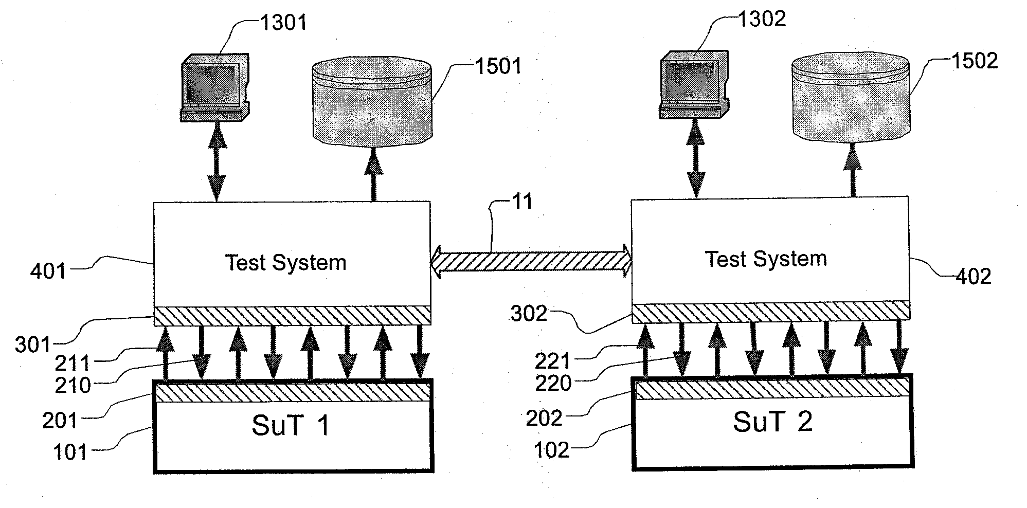
[0056]FIG. 1 shows test systems 401, 402 that are optimized for testing a closed system under test 101 or 102, respectively.

[0057]The systems under test 101, 102 usually consist of an avionics system controller or computer. In addition, each test system 401, 402 features an electrical interface 301, 302 that is respectively connected to an electrical interface 201, 202 of the system under test 101, 102 via the electrical wiring 210, 211, 220, 221. In the operating state of the systems under test, the interfaces 201, 202 of the systems under test are connected to sensors, actuators and other systems. In the test state, they are connected to the corresponding test systems 401,402 that simulate these sensors, actuators or other systems.

[0058]The test systems 401, 402 serve for simulating t...


PUM


Abstract

Modern high-end technology products such as aircraft consist of a number of individual systems that are controlled by independent electronic control units and increasingly interconnected. According to one exemplary embodiment of the present invention, a test system assembly for testing several such systems for an aircraft in parallel is disclosed, wherein a master network is provided in order to exchange data between the individual test systems and a control unit, and wherein original electrical wiring is provided between the test systems in order to directly interconnect the tested systems. The flexibility of system tests for aircraft may be increased in this fashion.

Description

REFERENCE TO RELATED APPLICATIONS[0001]This application claims the benefit of the filing date of U.S. Provisional Patent Application No. 60 / 937,246, filed 25 Jun. 2007, and German Patent Application No. 10 2007 029 137.1, filed 25 Jun. 2007, the disclosures of which are hereby incorporated herein by reference.FIELD OF THE INVENTION[0002]The present invention pertains to test systems. The present invention specifically pertains to a test system assembly for testing several systems under test in parallel, the utilization of a test system assembly in an aircraft and an aircraft or components of an aircraft that is / are connected to a test system assembly.TECHNOLOGICAL BACKGROUND OF THE INVENTION[0003]Test systems for electrical controllers that are also referred to as Systems under Test (SuT) in the following, may consist, for example, of so-called avionics components and are characterized in that the test systems are able to recreate or simulate the original environment of the system u...

Claims


Application Information

Patent Timeline
Patent Type & Authority Applications(United States)
IPC IPC(8): G06F17/50
CPCG01R31/008
Inventor STUNKEL, REINERLEMBCKE, RALPH
Owner AIRBUS OPERATIONS GMBH
Learn More