
Alignment Free Single-Ended Optical Probe and Methods for Spectroscopic Measurements in a Gas Turbine Engine

a gas turbine engine and single-ended technology, applied in the direction of instruments, gas-turbine engine testing, structural/machine measurement, etc., can solve the problems of difficult operation, difficult to interpret data, and extremely difficult measurements

Inactive Publication Date: 2010-07-08
ZOLO TECHNOLOGIES INC
View PDF24 Cites 26 Cited by
  • Summary
  • Abstract
  • Description
  • Claims
  • Application Information

AI Technical Summary

Benefits of technology

"The patent describes a method and apparatus for measuring the combustion property in a chamber within a casing. The apparatus includes a fiber assembly with a single mode transmit core and a multimode receive core means. The fiber assembly is connected to a port in the chamber wall. A detection beam is transmitted from the single mode fiber and reflected off a reflection surface within the chamber. The reflected beam is then measured by the multimode receive core means. The apparatus may also include a demultiplexer and a plurality of detectors for measuring each demultiplexed wavelength. The technical effect of this patent is to provide a more accurate and reliable method for measuring combustion properties in a chamber."

Problems solved by technology

While monitoring combustion properties in gas turbine engines would appear to have many potential benefits, making the measurements has proven extremely difficult.
The difficulty stems from two major sources.
First, the high-pressure and temperature in the immediate vicinity of the combustion zone (30-40 bar, 2200 K) creates an environment in which normal spectral features are highly distorted, leading to difficulty in interpreting data even if it can be obtained.
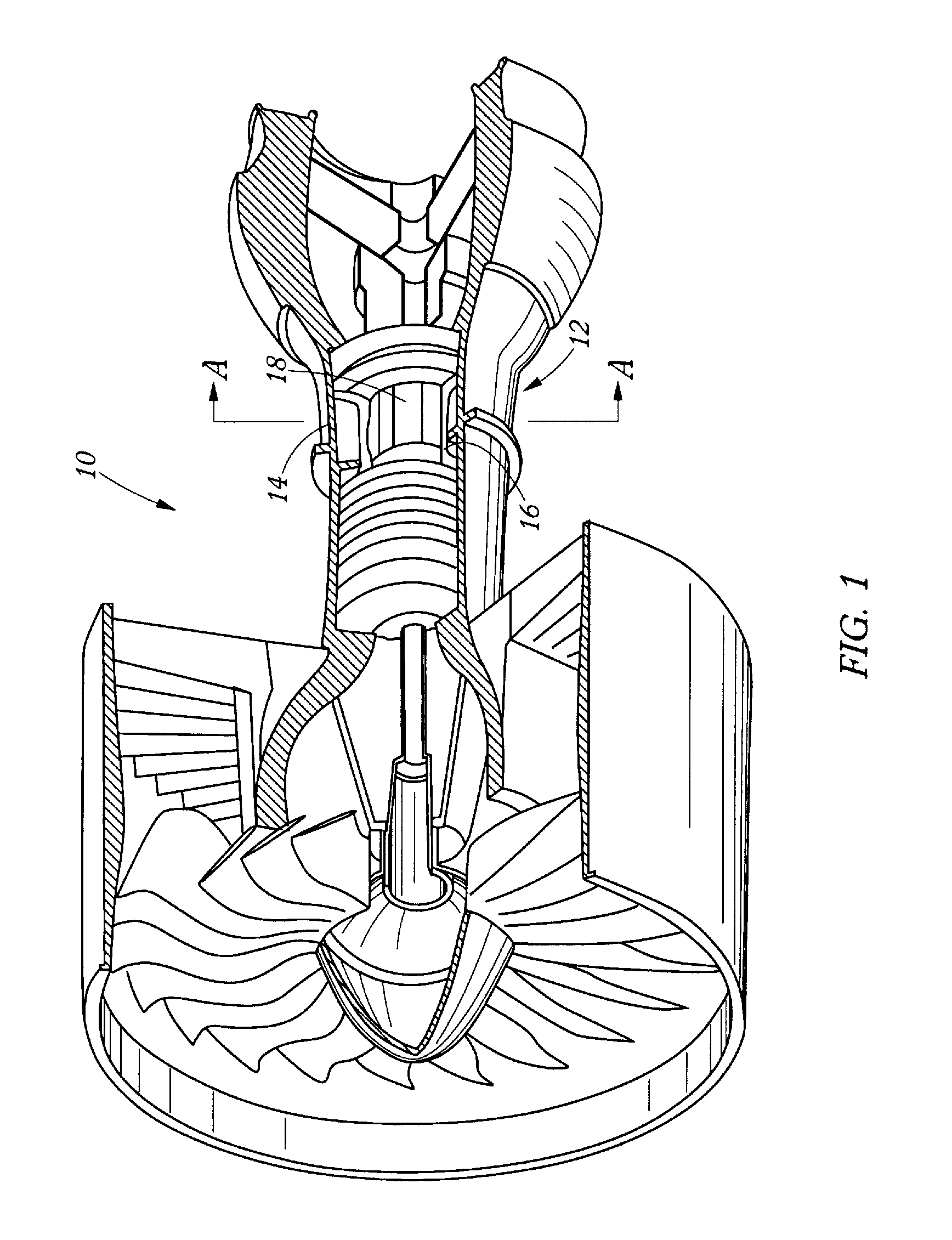
Second, making such measurements in an operating engine requires optical access; that is, a penetration or penetrations in the engine casing through which one can direct a laser beam over a line of sight.
This is very difficult to arrange in an operating gas turbine engines due to the harsh nature of the engine environment, the limited space available for monitoring components and the need to minimize impact on critical components.
The confined area in the vicinity of the combustion zone complicates effective access.
While potentially feasible, such a design is problematic because of the high-pressure, high-temperature environment and the difficulty of steering the beam at the severe angle required by the engine geometry.
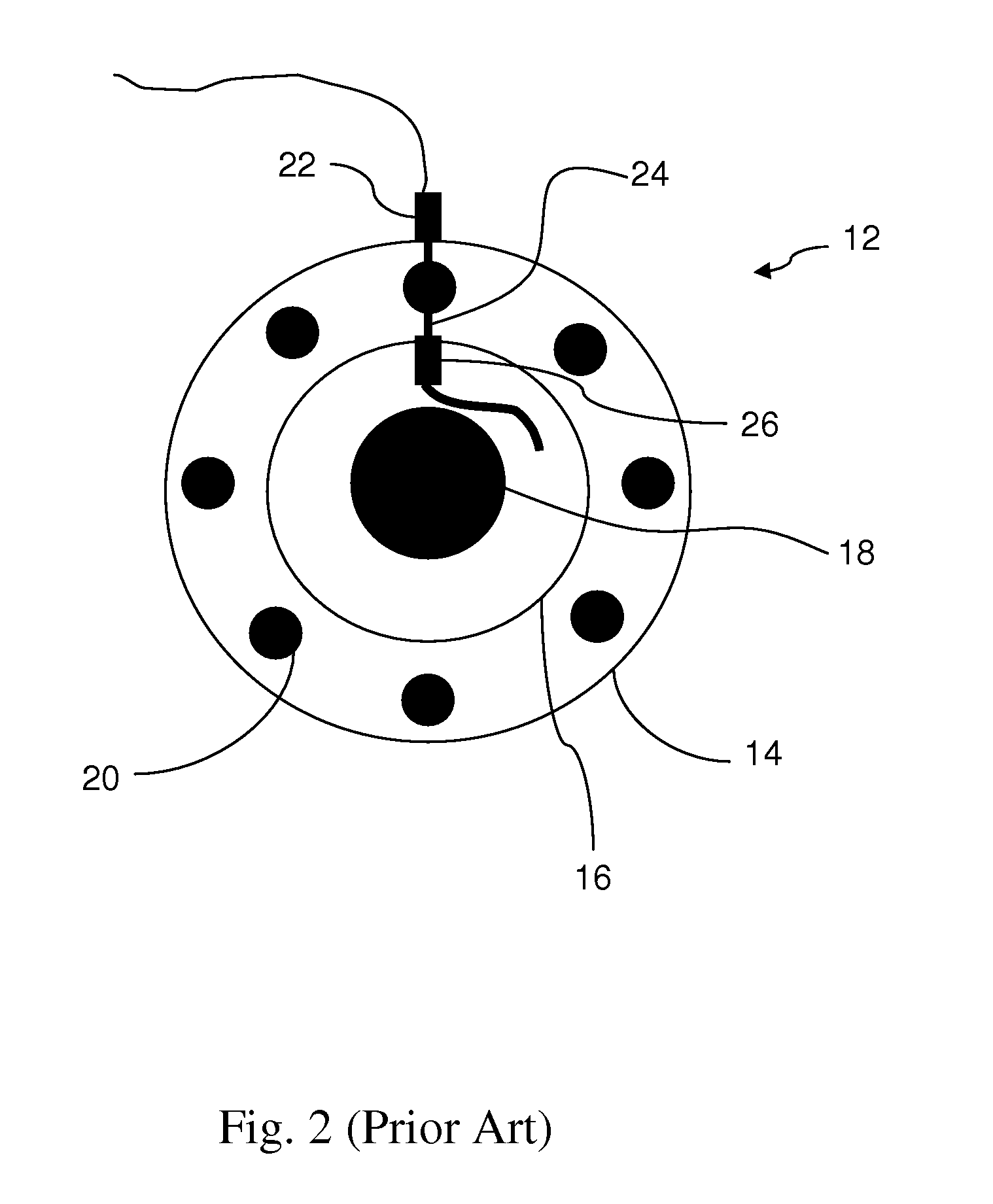
In certain implementations, however, it may be difficult or impossible to transmit a probe beam along a line which is normal to the inner casing 16 surface.
In addition, the inner casing may in certain instances prove to be an unsuitable reflective surface.

Method used


Image

  • Alignment Free Single-Ended Optical Probe and Methods for Spectroscopic Measurements in a Gas Turbine Engine
  • Alignment Free Single-Ended Optical Probe and Methods for Spectroscopic Measurements in a Gas Turbine Engine
  • Alignment Free Single-Ended Optical Probe and Methods for Spectroscopic Measurements in a Gas Turbine Engine

Examples


first embodiment

[0042]FIG. 8 is a schematic representation of the alignment free single-ended optical probe 72 deployed in operative association with a measurement volume 82 such as in or in proximity to a combustion zone of a gas turbine engine between an outer casing 84 and an inner casing 86. Alternatively, the inner casing 86 could be any normal reflective surface of the type discussed above. A laser beam is coupled to the single mode core 76 which emits a beam which is collimated by the lens 88 and reflected off the reflection surface 86 and thereafter received by the collimating lens 88 and further received in the plurality of multimode fiber cores 80. Sufficient emitted light is coupled by the collimating optic to each of the multimode fibers to provide for measuring desired combustion properties. The fiber bundle arrangement eliminates the need for realignment of the single mode transmit fiber relative to the multimode receive fibers during use.

[0043]Currently two structures and methods are...

second embodiment

[0044]an alignment free single-ended optical probe 72 is depicted in FIG. 10. Such an embodiment uses a dual core fiber 94 comprising a single mode transmit core 96 encased by a concentric integrally formed multimode receiving core 98, which comprises another embodiment of a multimode receive core means. Such a dual core fiber is available from Fibercore Ltd., Hampshire, UK. In use, a transmitted beam 95 from a laser is coupled to the single mode transmit core 96, directed to a collimating lens 88, bounced off a reflecting surface 86 in a measurement volume 82 and the reflected light is then collimated by the lens 88 and received in the receiving multimode core 98, as depicted in FIG. 11. Use of this type of fiber presents some difficulty in coupling the pitch light to the single mode transmit core 96 and decoupling the light and directing it to a detector after it is collected in the outer multimode core 98 since the transmitted and received light contains the same wavelengths. At ...


PUM

PropertyMeasurementUnit
temperatureaaaaaaaaaa
pressureaaaaaaaaaa
diameteraaaaaaaaaa

Abstract

A method of measuring the combustion property in a measurement volume within a casing defined in part by a casing wall. The method includes providing a port in the chamber wall. Also provided is a fiber assembly comprising a single mode transmit core surrounded by a multimode receive core means. The fiber assembly is operatively coupled to the port to provide optical communication between the fiber assembly and measurement volume. A detection beam capable of detecting a select combustion property is transmitted from the single mode fiber and reflected off a reflection surface within the chamber, the reflection surface being configured to reflect and optically couple at least a portion of the detection beam to the multimode receive core means. The detection beam optically coupled to the multimode receive core means is then measured.

Description

RELATED APPLICATIONS[0001]This application claims priority from U.S. Provisional Patent Application Ser. No. 61 / 143,109, filed Jan. 7, 2009, entitled “Alignment Free Single-Ended Optical Probe and Methods for Spectroscopic Measurements in a Gas Turbine Engine,” which is hereby incorporated by reference.TECHNICAL FIELD[0002]The present disclosure is directed toward an alignment free single-ended optical probe and method for monitoring and control of a combustion process, and more particularly toward a method and apparatus for spectroscopic measurements of combustion properties of a gas turbine engine.BACKGROUND OF THE INVENTION[0003]Laser-based spectroscopic instruments have been implemented in a variety of environments to extract measurement data. Laser-based measurement apparatus can be implemented in situ and offer the further advantage of high speed feedback suitable for dynamic process control. One technique for measuring combustion species such as gas composition, gas concentra...

Claims


Application Information

Patent Timeline
Patent Type & Authority Applications(United States)
IPC IPC(8): G01N21/00G01M15/14
CPCG01M15/14G01N21/8507G01N2021/8514
Inventor SAPPEY, ANDREW D.HOFVANDER, HENRIK
Owner ZOLO TECHNOLOGIES INC
Learn More