
Perimeter partition-valve with protected seals and associated small size process chambers and multiple chamber systems

a technology of process chambers and partition valves, applied in the field of substrate processing systems, can solve the problems of adverse impact on symmetry, affecting the uniformity and consistency of various process elements, and not being able to interface well with symmetry, so as to improve the safety of substrate placement members

Inactive Publication Date: 2010-07-01
SUNDEW TECH
View PDF73 Cites 15 Cited by
  • Summary
  • Abstract
  • Description
  • Claims
  • Application Information

AI Technical Summary

Benefits of technology

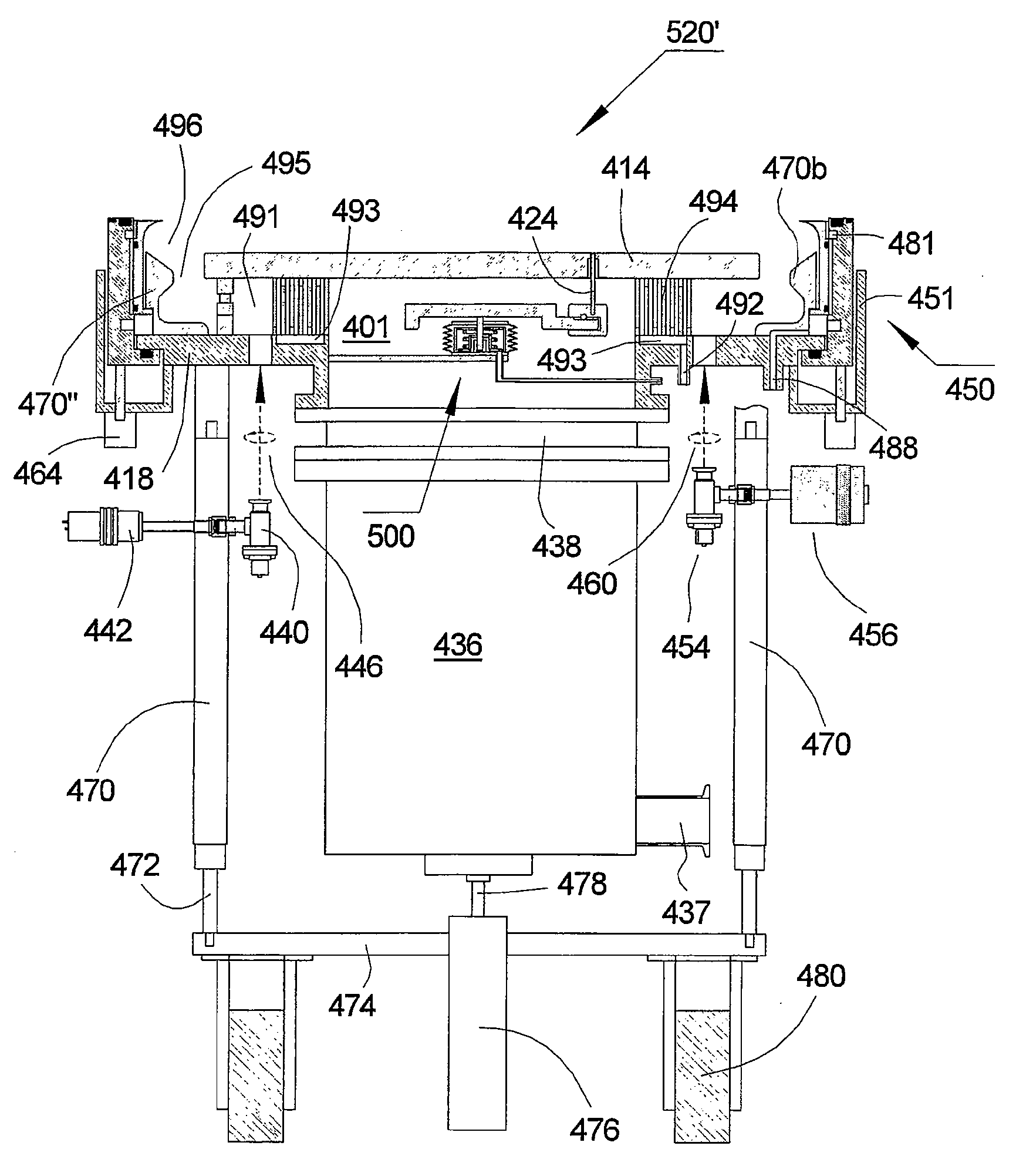
[0023]Embodiments within the invention circumvent the impairments of perimeter partition valves and substrate placement members to enable highly performing perimeter partitioned processing chambers with small footprint. It is the objective of this invention to substantially improve the performance of substrate processing chambers. In another scope the invention provides apparatus and method that reduce the size of processing chambers and processing systems. It is also within the scope of the invention to enhance the safety of substrate processing systems by providing fail-safe substrate placement members.
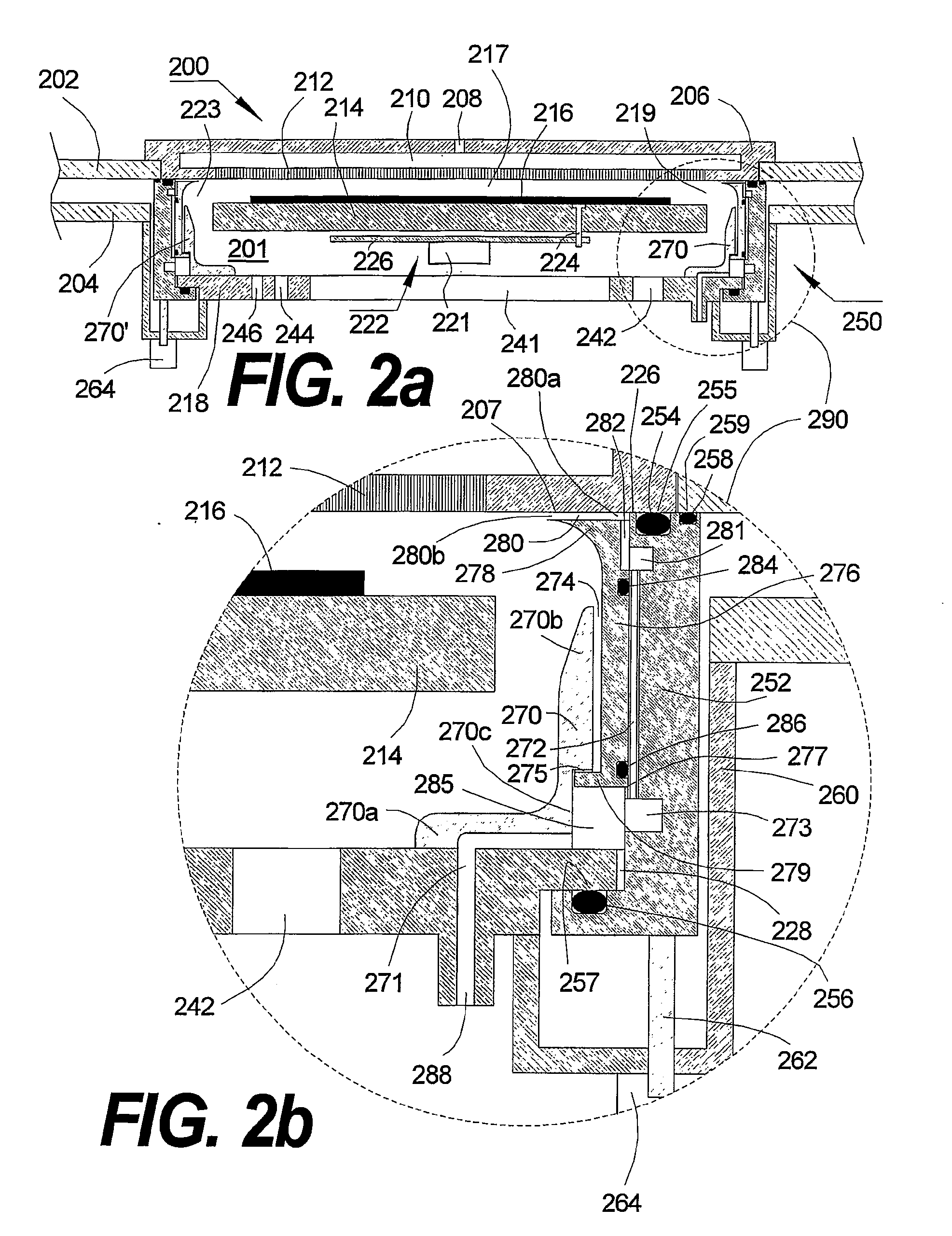
[0026]In a preferred implementation the substrate processing chamber further comprises an outer perimeter seal (258), a vessel perimeter sealing surface (259) and a lid (206) with a perimeter sealing surface (255). Preferably the outer perimeter seal is dispersed within the slide. The outer perimeter seal preferably forms a pressure tight communication with the vessel perimeter sealing surface when the PPV is actuated to the closed position and the perimeter seal preferably forms a pressure tight communication with the lid perimeter sealing surface when the PPV is preferably actuated to the closed position. Accordingly, the lid is preferably removable to provide access to the chamber and the perimeter seal while a pressure tight isolation between the chamber and the vessel is preferably maintained when the PPV is actuated to the closed position and the lid is removed. In a preferred implementation the substrate processing chamber includes a substrate placement assembly (850) which is preferably actuated to provide vertical substrate translation and the actuation is substantially contained within the process chamber. Preferably, the actuation is pneumatic. Preferably, the substrate processing chamber includes a pneumatic actuator (890) and the actuator is preferably operated by pressurizing the pneumatic actuator to translate the substrate vertically up and evacuating the pneumatic actuator to translate the substrate vertically down. Accordingly, the invention substantially enhances the safety of the processing chamber.
[0030]In another aspect the invention teaches a method for improving the safety of substrate placement members within a processing chamber comprising containing the wafer placement member within the processing chamber, containing the pneumatic actuator of the wafer placement member within the processing chamber and actuating the wafer placement member within the processing chamber where actuating comprises pressurizing the actuator to elevate the substrate placement member and evacuating the actuator to lower the substrate placement member.

Problems solved by technology

Substrate handling systems significantly add to the size and cost of the processing apparatus.
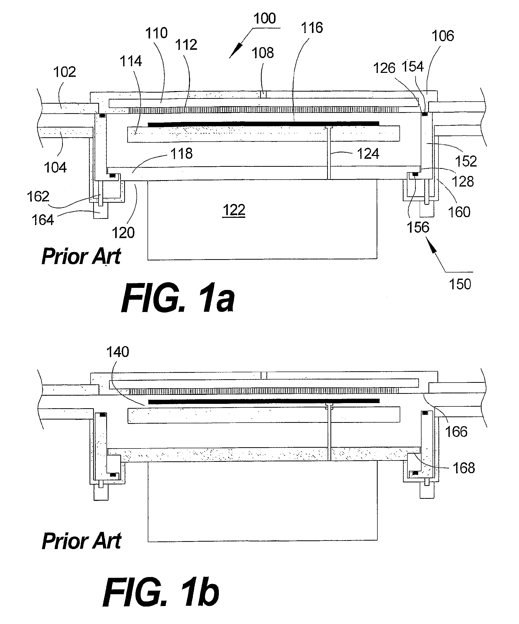
Current implementation of planar partitions, or slit valves, conventionally employs a flat design which does not interface well with the symmetry of round process chambers.
This inevitable cavity breaks the symmetry of the round process chamber with adverse impact on the symmetry, uniformity and consistency of various process elements, such as flow, plasma field, pressure and chemical transport.
In addition, the parasitical cavity acts as a “dead space”, creating flow turbulence that notoriously generates particles.
Such dead-space cavities are particularly detrimental to the performance and optimization of atomic layer deposition (ALD), an emerging cutting edge process technology.
Therefore, slit-valve-related asymmetry imposes an inevitable increase in chamber size.
Unfortunately, the relative impact of substrate process chambers on the overall size and cost of the processing system increases as the number of process chambers per system decreases making planar volume partitions such as planar slit-valves less favorable.
However, despite these indisputable advantages, perimeter partitioned systems continue to be unpopular.
Unfortunately, perimeter partitions also enhance problems that are inherent to volume partitions.
Most problematic, as well known to those who are skilled in the art, is the integrity and the cleanliness of the partition seals and related crevices.
As well known in the art, process chamber contamination and failure are significantly driven by the growth of undesired films and / or accumulation of contamination at exposed crevices between the slide and the housing, as well as the deterioration of the seals by exposure to harsh chemical and / or plasma environment.
Unfortunately, perimeter volume partitions typically introduce at least four times longer seals and related problematic slide-housing gaps.
Unfortunately, this prior art improvement does not completely resolve the problem, in particular, in the case of deposition processes.
However, the PSV apparatus of US patent application number 2003 / 0180458 is specific to the synchronously modulated flow and draw ALD (SMFD-ALD) method and does not provide a seal protected perimeter volume partition apparatus with easy application to other methods.
In addition, chambers defined with perimeter partitions lack the necessary wall area where essential accessories such as pressure gauges, pressure switches, electrical feeding ports (electrical feedthrough), sensors (such as temperature measurement, end-point detection, etc.), feeding ports, view ports, pumping ports, residual gas analyzers, feeding ports for in-situ cleaning gas, to name a few, are typically communicated with the chamber space through the chamber wall.
Process chambers typically have minimized usable space at both the top and the bottom ends.
The top end typically hosts process gas delivery members and is inherently unsuitable to communicate the accessories listed above with the process space.
The bottom end is typically substantially crowded with a cumbersome substrate placement member leaving only very limited unoccupied area.
Accordingly, conventional substrate placement members leave very limited unoccupied area at the bottom of process chambers that is substantially insufficient for relocating the above listed essentials.
Inevitably, this situation imposes an undesired chamber area increase to provide additional necessary space at the bottom end of the chamber.
During processing, perimeter crevices 126 and 128 at the top and the bottom seal areas, respectively, are exposed to the process ambient resulting in unacceptable deterioration and contamination and overall inferior performance.

Method used


Image

  • Perimeter partition-valve with protected seals and associated small size process chambers and multiple chamber systems
  • Perimeter partition-valve with protected seals and associated small size process chambers and multiple chamber systems
  • Perimeter partition-valve with protected seals and associated small size process chambers and multiple chamber systems

Examples


Embodiment Construction

A. Seal Protected Compact Perimeter Partition Valve

[0045]The perimeter partition valve (PPV) with perimeter seal protection according to the invention is practiced with a combination of gas plenum and a perimeter drift channel to effectively maintain a directional flow of inert gas out of the seal area. The perimeter gas plenum delivers a substantially unified flow of inert gas to the perimeter drift channel. The drift channel defines a high velocity flow of inert gas that minimizes the diffusion of reactive species to the seal area. Improved maintainability is achieved with removable perimeter shields (liners) wherein unavoidable deposition or condensation of film deposits is substantially limited onto easily removable parts. A removable sliding liner attached to the PPV slide provides for a smooth and round process chamber corner and a substantially long seal protecting drift channel. Complementary, a stationary liner integrates with the sliding liner to define a smooth gas flow p...


PUM

PropertyMeasurementUnit
lengthaaaaaaaaaa
inner diameteraaaaaaaaaa
outer diameteraaaaaaaaaa

Abstract

A seal-protected perimeter partition valve apparatus defines a vacuum and pressure sealed space within a larger space confining a substrate processing chamber with optimized geometry, minimized footprint, and 360° substrate accessibility. A compact perimeter partitioned assembly with seal protected perimeter partition valve and internally contained substrate placement member further provides processing system modularity and substantially minimized system footprint.

Description

CROSS-REFERENCE TO RELATED APPLICATIONS[0001]This application is a Divisional of U.S. patent application Ser. No. 10 / 567,319 filed on Oct. 23, 2006, which is a National Stage of PCT Application No. PCT / US04 / 025612 filed on Aug. 9, 2004, which PCT application claims the benefit of U.S. Provisional Application No. 60 / 493,872 filed Aug. 7, 2003; U.S. Provisional Application No. 60 / 499,276 filed Aug. 28, 2003; and U.S. Provisional Application No. 60 / 501,943 filed Sep. 11, 2003. All of the above patent applications, provisional, PCT, and non-provisional, are hereby incorporated by reference to the same extent as though fully contained herein.BACKGROUND OF THE INVENTION[0002]1. Field of the Invention[0003]This invention relates to the area of substrate processing systems and more specifically to a system and apparatus for transferring a substrate to a processing chamber and subsequently processing a substrate under sub-atmospheric pressure within a process chamber.[0004]2. Description of ...

Claims


Application Information

Patent Timeline
Patent Type & Authority Applications(United States)
IPC IPC(8): C23C16/00H01L21/677C23C16/44C23C16/455C23C16/54H01L21/00
CPCC23C14/566H01L21/68792C23C16/45519C23C16/54H01L21/67126H01L21/67161H01L21/67167H01L21/67173H01L21/67184H01L21/6719H01L21/67201H01L21/67742H01L21/67745H01L21/67748H01L21/68742H01L21/68764H01L21/68771H01L21/68785C23C16/4409
Inventor SNEH, OFER
Owner SUNDEW TECH
Learn More