Master Cylinder System for an Automotive Hydraulic Brake System and Automotive Hydraulic Brake System

Active Publication Date: 2010-07-01
LUCAS AUTOMOTIVE GMBH
View PDF12 Cites 20 Cited by
  • Summary
  • Abstract
  • Description
  • Claims
  • Application Information

AI Technical Summary

Benefits of technology

[0007]The object of the present invention is to provide a master cylinder arrangement and a correspondingly designed motor vehicle brake system of the previously described type, which are suitable for brake force boosting and which guarantee a more reliable mode of operation.
[0010]A development of the invention provides that the adjacent cylinder bores extend substantially parallel to one another. A space-saving arrangement of the inder bores is therefore possible.
[0012]In contrast to the initially discussed prior art, in which an actuation of the first piston arrangement is effected directly by means of the brake pedal, a development of the invention provides that in the normal operating situation the master cylinder arrangement according to the invention is actuated, not directly by means of a pedal actuation, but instead by means of an intermediate servo system in accordance with a pedal actuation and a resultant movement of the force input piston. Thus, this constructional variant of the invention provides that each piston arrangement comprises a pressure piston and a back-up piston, wherein enclosed between the respective pressure piston and the respective back-up piston is a servo chamber, which is chargeable with a pressure fluid from a pressure source. In this case, the back-up piston upon introduction of the pressure fluid into the servo chambers remains in a normal position, whereas the respective pressure piston is displaced in a brake-active manner. In this connection, it may further be provided that the servo chambers associated with the first piston arrangement and the second piston arrangement are jointly chargeable with pressure fluid for the brake-active increase of the fluid pressure in the first pressure chamber and in the second pressure chamber. The effect may therefore be achieved that both piston arrangements are activated with the same intensity, thereby resulting in a uniform braking performance. This is necessary particularly when there is also a wheel brake unit of a brake system associated in each case with a pressure chamber.
[0017]A development of the invention provides that the transmission element at its end facing the piston arrangements is of a cup-shaped design and receives in the cup a portion of the piston arrangements that faces towards it. The transmission element may therefore be of a longer design. This is necessary particularly if the transmission element is guided, preferably by means of at least two peripheral regions, in a linearly movable, tilt-proof manner in the housing. Given a correspondingly long design of the transmission element with suitable peripheral regions performing a guide function, a reliable take-up of axial forces as well as transverse forces is possible without any risk of tilting or binding of the transmission element.
[0019]With a view to simple and economical manufacture, a development of the invention provides that the piston arrangements are at least partially guided in guide bushes inserted into the housing. Because of the need to provide fluidproof guides for various components that are movable relative to one another, the respective surfaces, in particular the surfaces of receiving bores need to be of as high a quality and as insensitive as possible. This is costly above all in hollow bodies. With the previously mentioned variant the invention takes a different approach by using individual guide bushes, which are much easier to manufacture and may then be subsequently inserted into a housing blank and assume the required guide properties. In particular, in this connection it may be provided that the guide bushes are manufactured from corrosion-resistant and friction-reducing material.

Problems solved by technology

The disadvantageous effect of such a directly connected brake system is that the driver by means of his actuating activity at the brake pedal always influences the hydraulic pressure at the wheel brakes.
However, as soon as the driver reacts incorrectly to the actual braking situation by adjusting for example far too much or far too little brake pressure, the braking performance, in particular the braking distance and the track-keeping of the vehicle may be impaired, which in the worst-case scenario may lead to an accident.
A further drawback of this arrangement is that the two piston arrangements in the corresponding cylinder bores are hydraulically connected to one another.
This gives rise to the problem that in the event of a malfunction, in particular a leakage in the region of the piston arrangement moved directly by a brake pedal actuation, reliable activation of the piston arrangement disposed downstream of this piston arrangement is no longer possible.

Method used


Image

  • Master Cylinder System for an Automotive Hydraulic Brake System and Automotive Hydraulic Brake System
  • Master Cylinder System for an Automotive Hydraulic Brake System and Automotive Hydraulic Brake System
  • Master Cylinder System for an Automotive Hydraulic Brake System and Automotive Hydraulic Brake System

Examples


Embodiment Construction

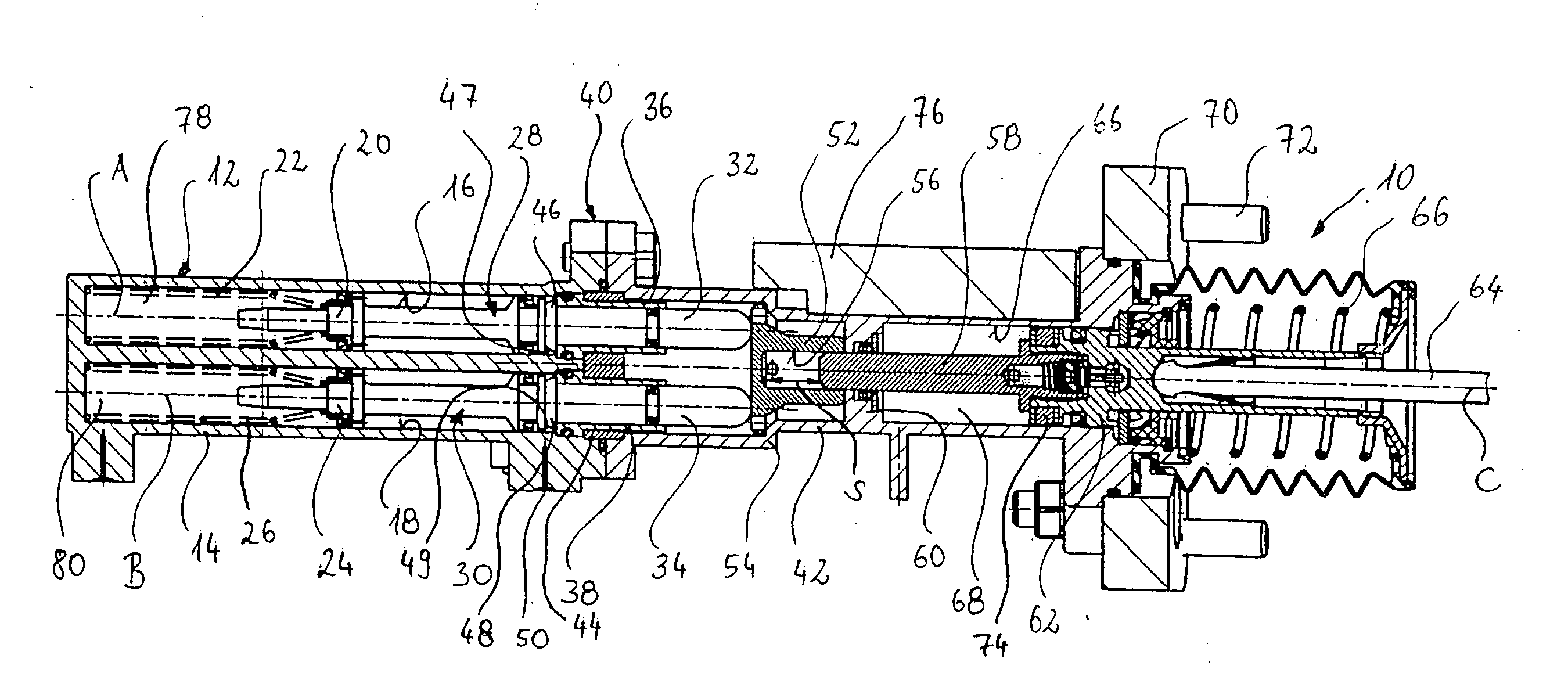
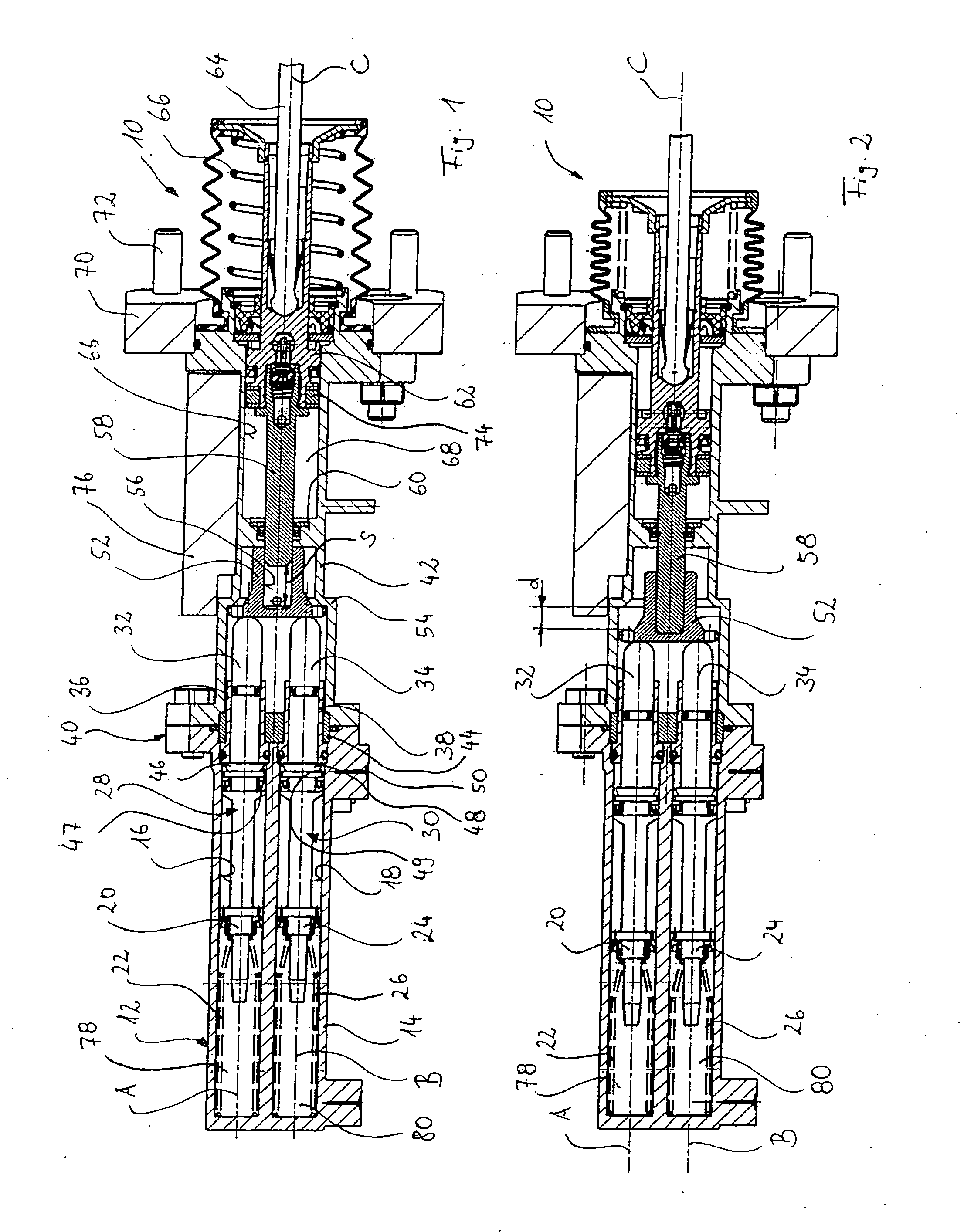
[0034]In FIG. 1 a master cylinder arrangement according to the invention is shown in a longitudinal sectional view and denoted generally by 10. It comprises a housing 12 of a multipart design, of which a first housing part 14 has a first cylinder bore 16 and, parallel thereto, a second cylinder bore 18, which run parallel along a first bore longitudinal axis A and a second bore longitudinal axis B.

[0035]Disposed in the first cylinder bore 16 is a first pressure piston 20, which is biased in FIG. 1 to the right by means of a resetting spring 22. Analogously thereto, a second pressure piston 24 is disposed in the second cylinder bore 18 and biased in FIG. 1 to the right by means of a resetting spring 26. The pressure pistons 20 and 24 are associated with respective first and second piston arrangements 28 and 30. The first piston arrangement 28 comprises in addition to the first pressure piston 20 a first back-up piston 32. The second piston arrangement 30 also comprises in addition to...


PUM


Abstract

The present invention relates to a master cylinder arrangement for a motor vehicle hydraulic brake system comprising a housing, in which two adjacent cylinder bores are provided, two piston arrangements, wherein a first piston arrangement is received in a first of the cylinder bores so as to be displaceable along a first bore longitudinal axis and wherein a second piston arrangement is received in a second of the cylinder bores so as to be displaceable along a second bore longitudinal axis, a force input piston, which is connectable or connected to a brake pedal, wherein in accordance with a movement of the force input piston the first piston arrangement and the second piston arrangement are displaceable, wherein the first piston arrangement with the housing delimits a first pressure chamber, which is fluidically connected to a hydraulic brake system, and wherein the second piston arrangement with the housing delimits a second pressure chamber, which is fluidically connected to the hydraulic brake system. In this master cylinder arrangement it is provided that between the first piston arrangement as well as the second piston arrangement and the force input piston a separate transmission element is disposed, which is movable into joint abutment with the first piston arrangement and the second piston arrangement.

Description

CROSS-REFERENCE TO RELATED APPLICATIONS[0001]This application is a National Stage of International Application No. PCT / EP2006 / 007328 filed Jul. 25, 2006, the disclosures of which are incorporated herein by reference, and which claimed priority to German Patent Application No. 10 2005 037 792.0 filed Aug. 10, 2005, the disclosures of which are incorporated herein by reference.BACKGROUND OF THE INVENTION[0002]The present invention relates to a master cylinder arrangement according to the preamble of claim 1.[0003]Such a master cylinder arrangement is known for example from the document DE 37 15 209 A1, and corresponding U.S. Pat. No. 4,794,757, both of which are incorporated by reference herein. This is designed in a similar manner to a tandem master cylinder arrangement but is much more space-saving because the two piston arrangements act in the mutually adjacent cylinder bores, which are hydraulically connected to one another. During a braking operation, a brake pedal is used to int...

Claims


Application Information

Patent Timeline
IPC IPC(8): B60T13/66B60T11/20
CPCB60T7/042B60T8/267B60T8/4072B60T2270/40B60T8/441B60T11/203B60T2230/00B60T8/4077B60T7/04B60T8/40B60T11/20
Inventor SCHLUTER, PETERMONIKA, MATTHEI
Owner LUCAS AUTOMOTIVE GMBH
Why Eureka
Try Eureka