Liquid fuel property detection system
- Summary
- Abstract
- Description
- Claims
- Application Information
AI Technical Summary
Benefits of technology
Problems solved by technology
Method used
Image
Examples
first embodiment
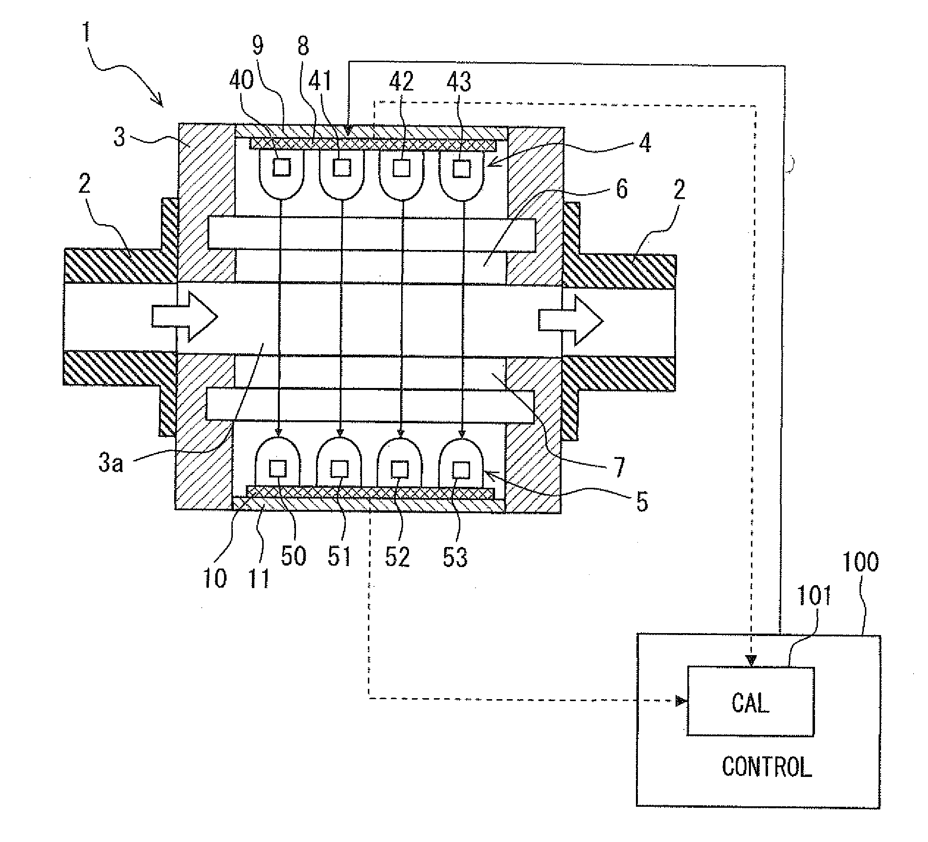
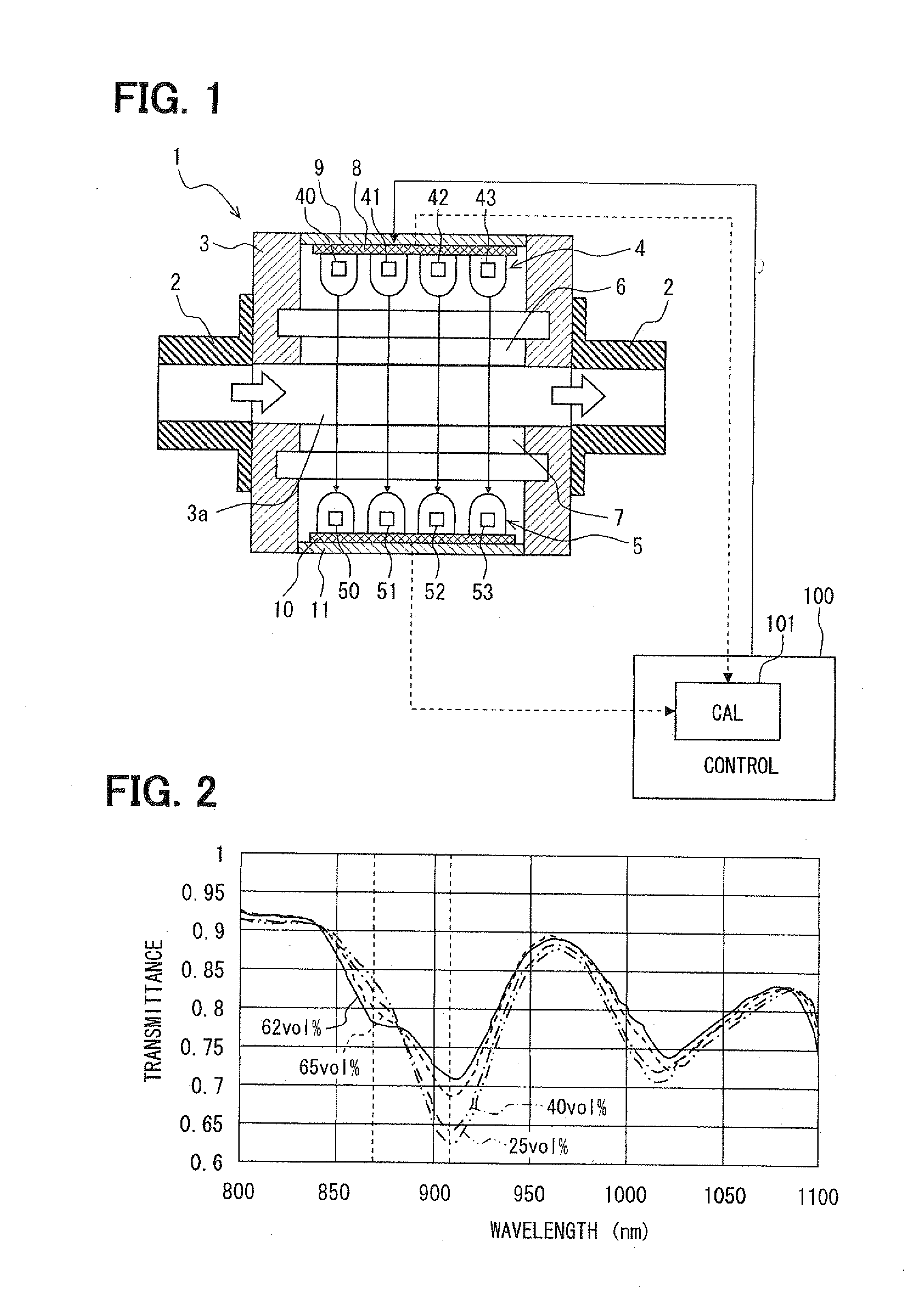
[0023]Referring to FIG. 1, a liquid fuel property detection apparatus is provided with a fuel property sensor 1 and an electronic control unit 100, which detect a specific hydrocarbon component in liquid fuel supplied to an engine in an engine control system of a vehicle.
[0024]The engine control system has a fuel pipe 2 for supplying fuel under control of the control unit 100 and other parts (not shown). The control unit 100 includes a central processing unit (CPU) 101 as a calculation unit, an input circuit for receiving various signals and an output circuit for outputting signals to drive various actuators, so that fuel injection amount, fuel injection time, spark ignition time, throttle valve position, and the like are controlled. The control unit 100 also includes memories such as a ROM, a RAM and the like, which store calculation programs, control programs and the like, which are executed by calculation unit 101.
[0025]Gasoline, which is liquid fuel for the engine, includes a va...
second embodiment
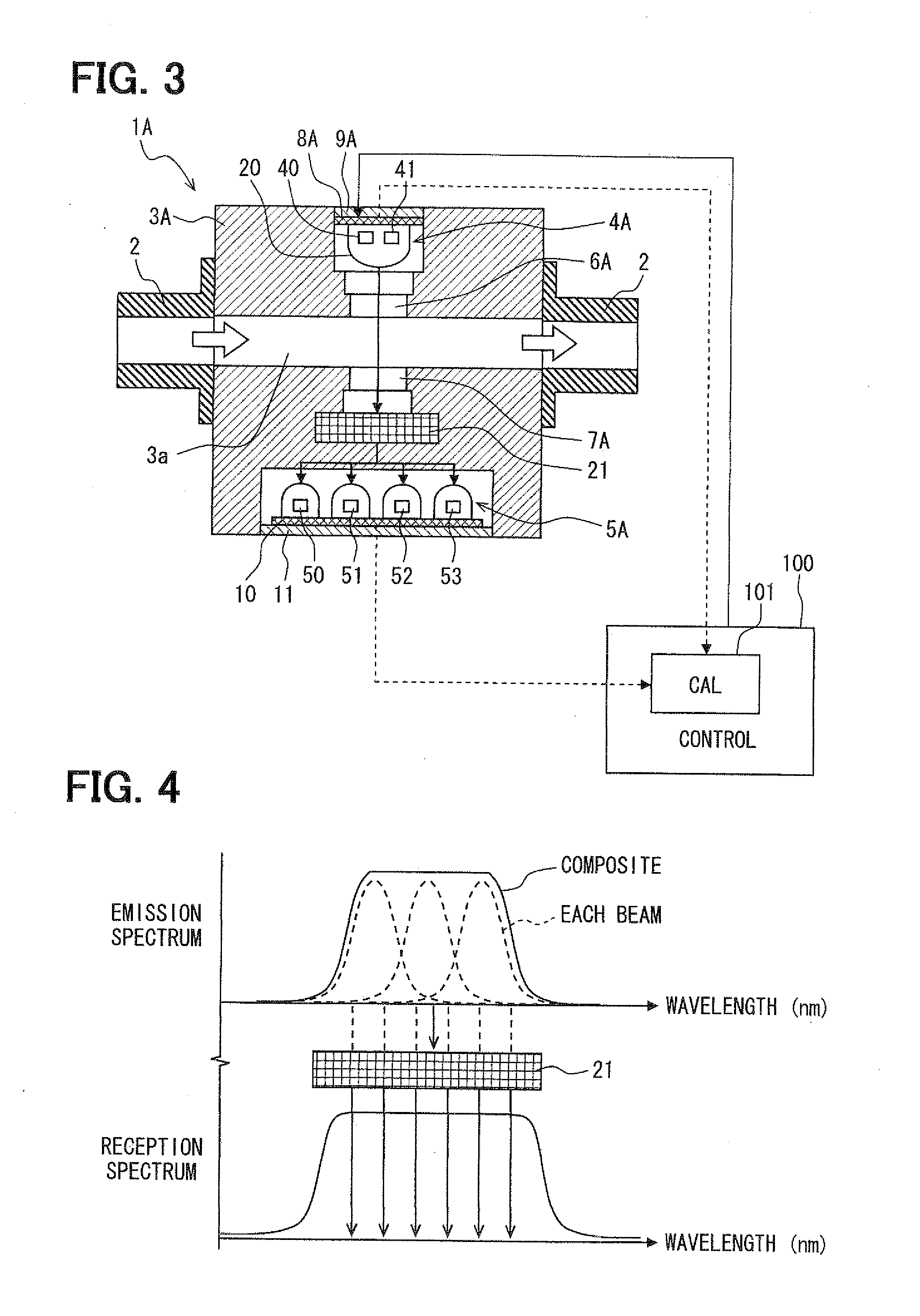
[0058]A fuel property sensor 1A according to the second embodiment is shown in FIG. 3. In the second embodiment, a light emitting device 4A and a light receiving device 5A of the fuel property sensor 1A are configured to have the light emitting spectrum and the light reception spectrum, which are shown in FIG. 4 in a simplified form.
[0059]In the fuel property sensor 1A, the light emitting device 4A includes a plurality of (two) light emitting elements (first light emitting element 40, second light emitting element 41), which are less in number than light receiving elements 50 to 53 in the light receiving device 5A. The light emitting device 4A further includes a light combining device 20, which produces composite light by combining the light beams of the light emitting elements 40 and 41. A light separating device 21 is provided between the passage 3a and the light receiving device 5A, so that the composite light having passed through the fuel is separated into a plurality of light ...
third embodiment
[0068]A fuel property sensor 16 according to the third embodiment is shown in FIG. 5. A light emitting device 4B and a light receiving device 5B of the fuel property sensor 1B are configured to have the light emission spectrum and the light reception spectrum, which are shown in FIG. 6 in a simplified form. That is, in FIG. 6 only first and second light beams are shown although more light beams are emitted in the third embodiment.
[0069]In the third embodiment, the light emitting device 4B have four light emitting elements (first light emitting element 50, second light emitting element 51, third light emitting element 52, fourth light emitting element 53) and the light receiving device 5B has only one light receiving element 50. The light emitting elements 40 to 43 emit respective light beams having different wavelengths, which are suitable for detection of the specific component. The light emitting elements 40 to 43 are driven to emit respective lights separately at different time p...
PUM
 Abstract
Description
Claims
Application Information
 - R&D Engineer
- R&D Manager
- IP Professional
- Industry Leading Data Capabilities
- Powerful AI technology
- Patent DNA Extraction
Browse by: Latest US Patents, China's latest patents, Technical Efficacy Thesaurus, Application Domain, Technology Topic, Popular Technical Reports.
© 2024 PatSnap. All rights reserved.Legal|Privacy policy|Modern Slavery Act Transparency Statement|Sitemap|About US| Contact US: help@patsnap.com


