Magnetic antenna and antenna device

Active Publication Date: 2010-06-24
MURATA MFG CO LTD
View PDF3 Cites 10 Cited by
  • Summary
  • Abstract
  • Description
  • Claims
  • Application Information

AI Technical Summary

Benefits of technology

[0014]The present invention has been developed in view of the above-described problems, and it is an object of the present invention to provide a magnetic antenna and an antenna device that increase the packaging density of the portion where the magnetic antenna is mounted in an electronic apparatus, and suppresses the degradation of antenna performance.

Problems solved by technology

However, when two of the magnetic antennas shown in FIG. 1 are provided to configure a pair of magnetic antennas by connecting the coil conductors thereof such that the currents flowing in the two coil conductors have the same phase, problems are encountered, such as described below with reference to FIGS. 1, 2A, and 2B.
Hence, the magnetic flux passing through the winding centers of the coil conductors is limited to magnetic flux that enters the magnetic cores 13 through the end portions thereof, thus causing a decrease in antenna performance (i.e., a decrease in gain).

Method used


Image

  • Magnetic antenna and antenna device
  • Magnetic antenna and antenna device
  • Magnetic antenna and antenna device

Examples


first embodiment

[0038]A magnetic antenna according to the present invention will be described with reference to FIGS. 3 and 4.

[0039]FIG. 3A is a development diagram of a flexible substrate 23 used for a magnetic antenna 20, FIG. 3B is a sectional view of the magnetic antenna 20, and FIG. 3C is a sectional view showing the positional relationship between a circuit substrate 31 of an electronic apparatus and the magnetic antenna 20.

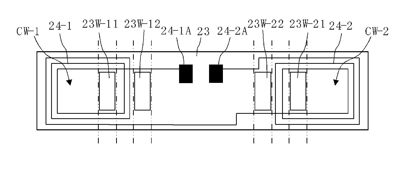
[0040]Referring to FIG. 3A, the flexible substrate 23 has spiral coil conductors 24-1 and 24-2 formed thereon, and respective opening portions of the spiral coil conductors have conductor-opening-side through holes 23W-11 and 23W-21 formed therein into which the magnetic cores 13 are inserted. The flexible substrate 23 has non-coil-conductor-forming-area through holes 23W-12 and 23W-22, into which the magnetic cores 13 are inserted, formed in areas where the spiral coil conductors 24-1 and 24-2 are not formed.

[0041]Referring to FIG. 3B, a magnetic core 13-1 is provided on ...

second embodiment

[0052]FIG. 5A is a plan view of a magnetic antenna 21 prior to assembly according to the invention. FIG. 5B is a plan view after assembly and FIG. 5C is a sectional view thereof.

[0053]A flexible substrate 23 has spiral coil conductors 24-1 and 24-2 formed thereon, and respective winding center portions of the coil conductors 24-1 and 24-2 have conductor-opening-side through holes 23W-11 and 23W-21 formed therein. The flexible substrate 23 has non-coil-conductor-forming-areathrough holes 23W-12 and 23W-22 formed therein, each of which is a substantially U-shaped hole, i.e., a hole made of slits forming three sides of a quadrangle.

[0054]In this example, the magnetic cores 13-1 and 13-2 are formed such that portions thereof which extend through the conductor-opening-side through holes 23W-11 and 23W-21 and the non-coil-conductor-forming-area through holes 23W-12 and 23W 22 of the flexible substrate 23 have smaller widths than outer portions, which are made wide.

[0055]The magnetic core ...

third embodiment

[0060]FIG. 6A is a development diagram of a flexible substrate 23 used for a magnetic antenna 22 according to the invention, and FIG. 6B is a sectional view thereof. In this example, the flexible substrate 23 has, as another coil conductor, a center portion coil conductor 25 provided thereon between the positions where the two coil conductors 24-1 and 24-2 are formed.

[0061]The center portion coil conductor 25 is arranged at such a position as to be able to be linked with magnetic flux passing by the center portion of the flexible substrate 23, as shown by dotted lines in FIG. 6B. These three coil conductors are connected in series such that magnetic flux passing in the directions shown in FIG. 6B induces currents having the same phase in the two coil conductors 24-1 and 24-2, and the center portion coil conductor 25.

[0062]In this manner, by providing the center portion coil conductor 25, electromotive force due to the center portion coil conductor 25 is applied, whereby the antenna ...


PUM


Abstract

There is provided a magnetic antenna and an antenna device that increase the packaging density of a portion where the magnetic antenna is mounted in an electronic apparatus, and suppresses degradation of antenna performance. A flexible substrate has first and second substantially spiral-shaped coil conductors formed thereon. Conductor-opening-side through holes are formed in the respective conductor openings of the coil conductors, and non-coil-conductor-forming-area through holes are formed in areas in which the coil conductors are not formed. First and second magnetic cores are arranged so as to extend through the respective conductor-opening-side through holes from a first main surface of the flexible substrate and to extend through the respective non-coil-conductor-forming-area through holes in a direction from a second main surface side to the first main surface of the flexible substrate.

Description

CROSS REFERENCE TO RELATED APPLICATIONS[0001]The present application claims priority to Japanese Patent Application No. 2008-327416 filed Dec. 24, 2008, the entire contents of the application being incorporated herein by reference in their entirety.BACKGROUND OF THE INVENTION[0002]1. Field of the Invention[0003]The present invention relates to a magnetic antenna and an antenna device used for radio frequency identification (RFID) systems, etc., that communicate with external apparatuses via electromagnetic signals.[0004]2. Description of the Related Art[0005]Mobile electronic apparatuses, such as cellular phones and data readers / writers, used in increasingly popular RFID systems, communicate with each other using respective antennas provided therein for information communication.[0006]In a mobile electronic apparatus, in particular, there is a strong demand for a high performance, low cost and smaller size antenna. As an antenna that satisfies such requirements, a magnetic antenna h...

Claims


Application Information

Patent Timeline
IPC IPC(8): H01Q7/08H01Q1/22
CPCG06K7/10316H01Q7/06H01Q1/38H01Q1/2208
Inventor KUBO, HIROYUKIITO, HIROMITSUYOSUI, KUNIAKI
Owner MURATA MFG CO LTD
Why Eureka
Try Eureka