
Electronic ballast for restarting high-pressure discharge lamps in various states of operation

a high-pressure discharge and electronic ballast technology, applied in the field of electronic ballasts, can solve the problems of dielectric breakdown and require a longer time period for ignition, and achieve the effect of easy restarting a high-pressure discharge lamp

Inactive Publication Date: 2010-06-24
PANASONIC CORP
View PDF2 Cites 9 Cited by
  • Summary
  • Abstract
  • Description
  • Claims
  • Application Information

AI Technical Summary

Benefits of technology

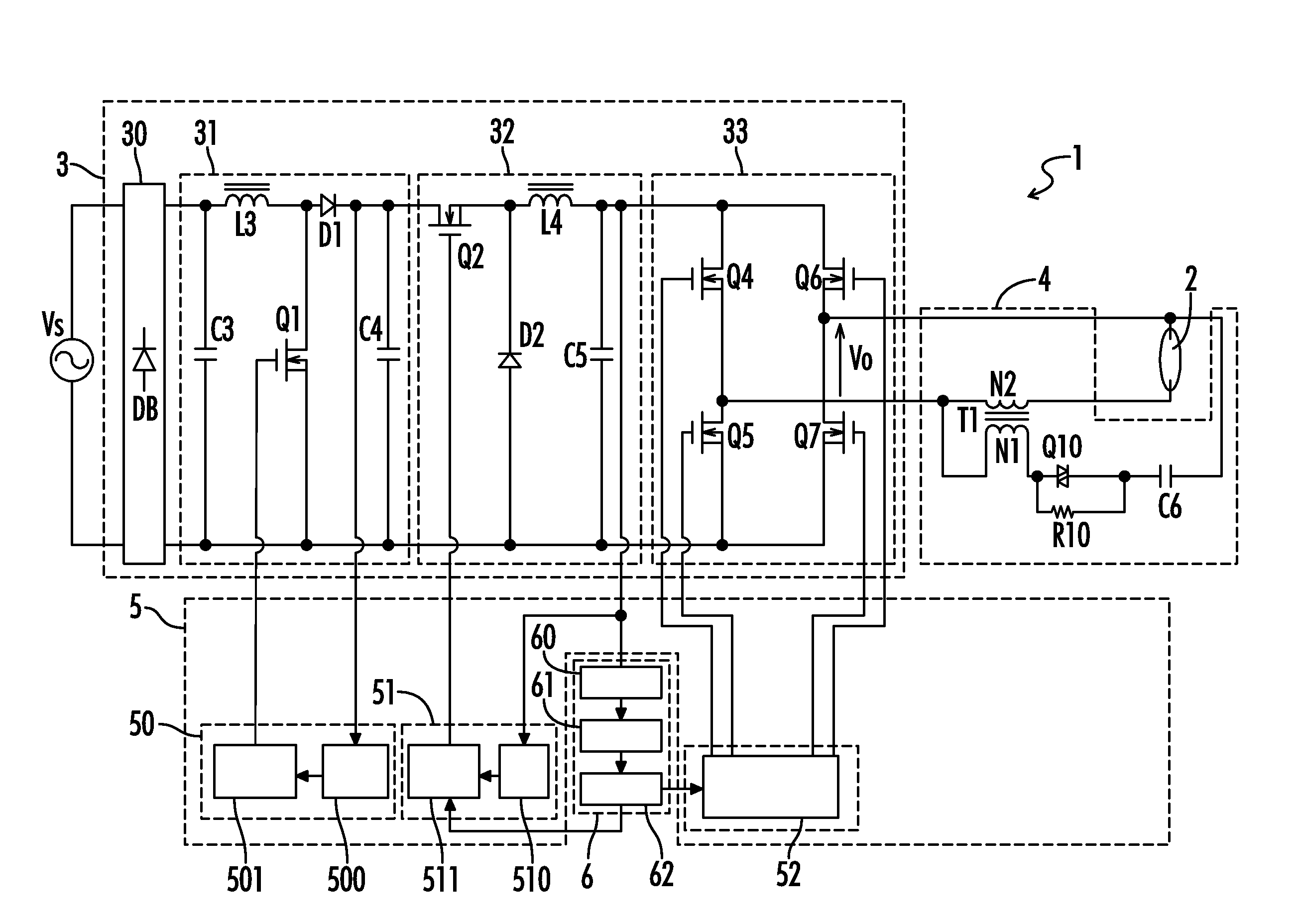
[0015]The present invention was achieved by taking the above problems into consideration, having an object to provide a high pressure discharge lamp ballast for easily restarting a high-pressure discharge lamp even if the lamp is extinguished prior to achieving stable lighting, and for bringing the lamp into various states of operation upon re-ignition.

Problems solved by technology

However, applying the voltage of several tens of kV to the conventional high-pressure discharge lamp 2 as shown in FIG. 15 will result in a dielectric breakdown in the vicinity of an Edison base 20 without application of a voltage required for the arc tube 21.
However, electrons which constitute discharge are consumed by iodide and the lighting is extinguished, thereby requiring a longer time period for ignition than that in usual ignition.
However, a high-pressure discharge lamp which is extinguished prior to achieving steady state operation can be brought into various kinds of states which differ from an initial (cold) ignition state, and it is therefore not necessarily ignited even if a high pressure discharge lamp ballast repeats the fixed ignition operation that has been established in advance.

Method used


Image

  • Electronic ballast for restarting high-pressure discharge lamps in various states of operation
  • Electronic ballast for restarting high-pressure discharge lamps in various states of operation
  • Electronic ballast for restarting high-pressure discharge lamps in various states of operation

Examples


Embodiment Construction

[0054]Throughout the specification and claims, the following terms take at least the meanings explicitly associated herein, unless the context dictates otherwise. The meanings identified below do not necessarily limit the terms, but merely provide illustrative examples for the terms. The meaning of “a,”“an,” and “the” may include plural references, and the meaning of “in” may include “in” and “on.” The phrase “in one embodiment,” as used herein does not necessarily refer to the same embodiment, although it may. The term “coupled” means at least either a direct electrical connection between the connected items or an indirect connection through one or more passive or active intermediary devices. The term “circuit” means at least either a single component or a multiplicity of components, either active and / or passive, that are coupled together to provide a desired function. The term “signal” means at least one current, voltage, charge, temperature, data or other signal. Where either a f...


PUM


Abstract

A high-pressure discharge lamp ballast is provided for igniting and re-igniting a high-pressure discharge lamp in various states of operation. A power supply circuit is coupled to a power source and supplies AC power to the lamp. An ignition voltage generating circuit supplies a high-voltage ignition pulse for igniting the lamp. A pulse control circuit alternatively controls the ignition voltage generating circuit in a first control mode to provide the high-voltage ignition pulses for a first time period and in a second control mode to delay the high-voltage ignition pulses for a second time period. An abnormality detection circuit detects an abnormal lighting state of the lamp wherein a measured condition of the lamp corresponds to a predetermined condition. The pulse control circuit increases a ratio of the second time period relative to the first time period upon detection of an abnormal lighting state of the lamp by the abnormality detection circuit.

Description

[0001]A portion of the disclosure of this patent document contains material that is subject to copyright protection. The copyright owner has no objection to the reproduction of the patent document or the patent disclosure, as it appears in the U.S. Patent and Trademark Office patent file or records, but otherwise reserves all copyright rights whatsoever.CROSS-REFERENCES TO RELATED APPLICATIONS[0002]This application claims benefit of the following patent application(s) which is / are hereby incorporated by reference: Japan Patent Application No. 2008-300154, filed Nov. 25, 2008.STATEMENT REGARDING FEDERALLY SPONSORED RESEARCH OR DEVELOPMENT[0003]Not ApplicableREFERENCE TO SEQUENCE LISTING OR COMPUTER PROGRAM LISTING APPENDIX[0004]Not ApplicableBACKGROUND OF THE INVENTION[0005]The present invention relates generally to ballasts for use in turning on a high-pressure discharge lamp. More particularly, the present invention relates to electronic ballasts configured to restart high-pressure...

Claims


Application Information

Patent Timeline
Patent Type & Authority Applications(United States)
IPC IPC(8): H05B41/30
CPCH05B41/2881Y02B20/204H05B41/386H05B41/2925H05B41/2886H05B41/2887H05B41/384Y02B20/00
Inventor YUFUKU, AKIRAKAMOI, TAKESHI
Owner PANASONIC CORP
Learn More