Apparatus of light source

a light source and apparatus technology, applied in the direction of discharge tube/lamp details, discharge tube luminescnet screens, lamp details, etc., can solve the problems of difficult uniform formation of large area cathode structures, high temperature after being powered, power consumption, etc., and achieve the effect of convenient fabrication

Inactive Publication Date: 2010-06-24
IND TECH RES INST
View PDF4 Cites 2 Cited by
  • Summary
  • Abstract
  • Description
  • Claims
  • Application Information

AI Technical Summary

Benefits of technology

[0009]The present invention is directed to an apparatus of light source, which can be easily fabricated into a flat light source without requiring a very high degree of vacuum, and the fluorescent materials can be selected, for example, to generate ultraviolet light source, infrared light, visible light, and so on.

Problems solved by technology

The conventional apparatus of light source, such as a bulb, generates a visible light source through a filament, resulting in high temperature after being powered on.
The gas discharge mechanism is easy to realize and has a simple structure, but the plasma is required to be generated in the processes, and thus it is power consuming.
In such a manner, it is difficult to uniformly form a large area cathode structure.
Furthermore, the distance between the cathode and anode in the field emission is required to be accurately controlled, and thus the requirements for spacer specification is very strict, and the vacuum package is also one of the problems.

Method used


Image

  • Apparatus of light source
  • Apparatus of light source
  • Apparatus of light source

Examples


Embodiment Construction

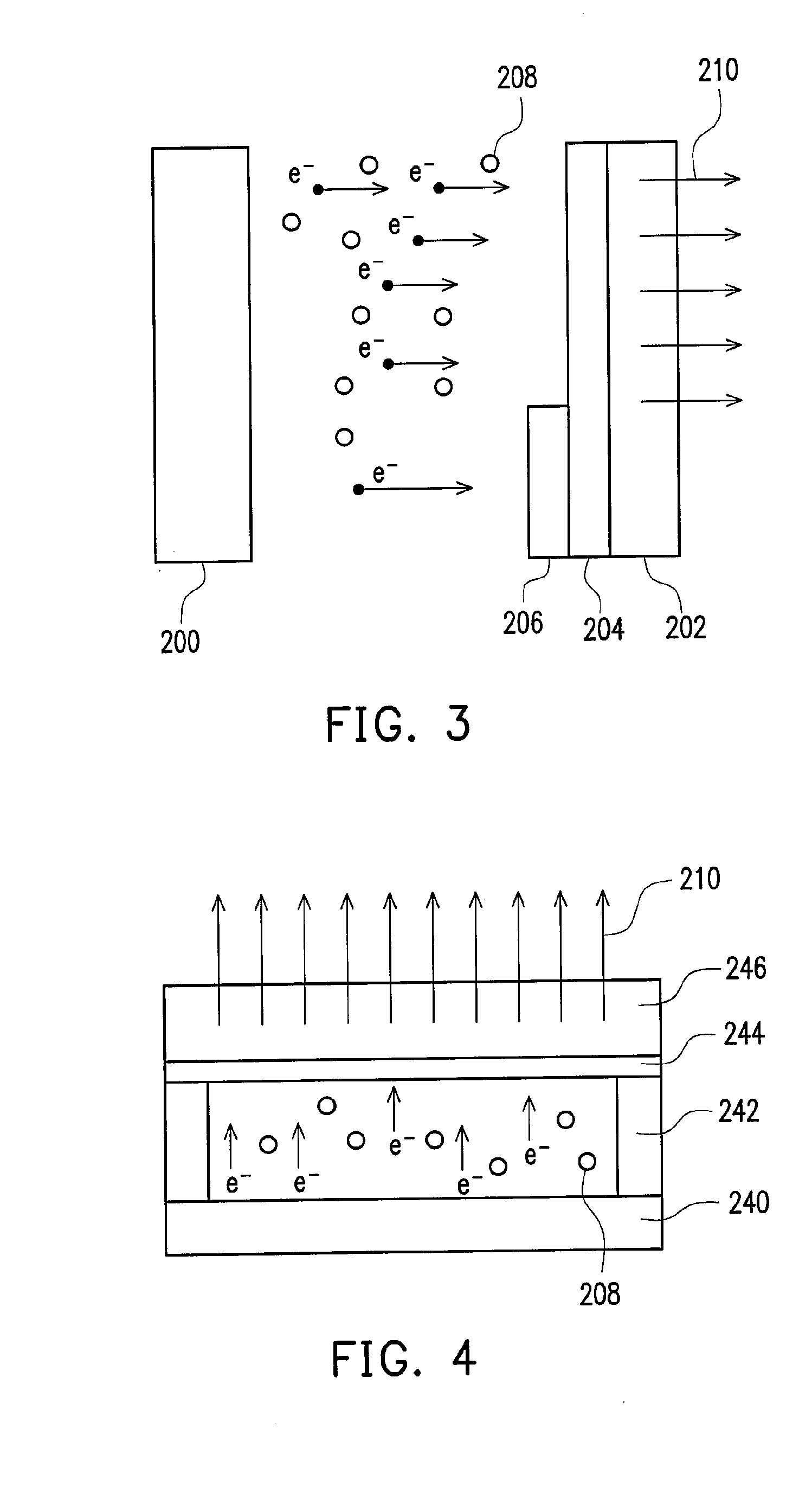
[0023]The present invention provides an apparatus of light source, which utilizes a basic mechanism of gas discharge, and can achieve a field emission effect by controlling the vacuum degree of the gas. Thus, the apparatus of light source of the present invention can be easily fabricated into a uniform flat light source. Fluorescent materials can further be selected, for example, to generate a flat ultraviolet light source or other visible light, infrared light, and so on.

[0024]The apparatus of light source provided by the present invention utilizes the gas conduction characteristic to lead out a sufficient amount of electrons from the cathode. These electrons fly in a thin gas. As the electron mean free path in the thin gas is long, a sufficient amount of electrons will still directly impact, for example, the fluorescent powder material on the anode, so as to emit light. This fluorescent powder would be excited by electrons to emit light. If an ultraviolet light is required, the el...


PUM


Abstract

An apparatus of light source includes a cathode structure, an anode structure, a fluorescent layer, and a low-pressure gas layer. The fluorescent layer is located between the cathode structure and the anode structure. The low-pressure gas layer is filled between the cathode structure and the anode structure, and has the function of electric conduction. The low-pressure gas layer has an electron mean free path, allowing most of electrons to directly impact the fluorescent layer under an operation voltage.

Description

CROSS-REFERENCE TO RELATED APPLICATION[0001]This is a continuation-in-part application of patent application Ser. No. 11 / 683,440, filed on Mar. 8, 2007, which claims the priority benefit of Taiwan application serial no. 95149963, filed on Dec. 29, 2006. The entirety of each of the above-mentioned patent applications is hereby incorporated by reference herein and made a part of this specification.BACKGROUND OF THE INVENTION[0002]1. Field of the Invention[0003]The present invention relates to an apparatus of light source. More particularly, the present invention relates to an apparatus of flat light source, for example, an apparatus of flat light source capable of generating a desired light.[0004]2. Description of Related Art[0005]Apparatuses of light source are widely used in daily life. The conventional apparatus of light source, such as a bulb, generates a visible light source through a filament, resulting in high temperature after being powered on. The light source of such a bulb ...

Claims


Application Information

Patent Timeline
IPC IPC(8): H01J1/62
CPCH01J63/06H01J63/02
Inventor CHEN, SHIH-PULI, JUNG-YULIN, YI-PINGLIN, WEI-CHIHCHO, LIAN-YI
Owner IND TECH RES INST
Why Eureka
Try Eureka