
Method for sensing gas composition and pressure

Active Publication Date: 2010-06-24
INSTITUT NATIONAL D'OPTIQUE
View PDF8 Cites 21 Cited by
  • Summary
  • Abstract
  • Description
  • Claims
  • Application Information

AI Technical Summary

Benefits of technology

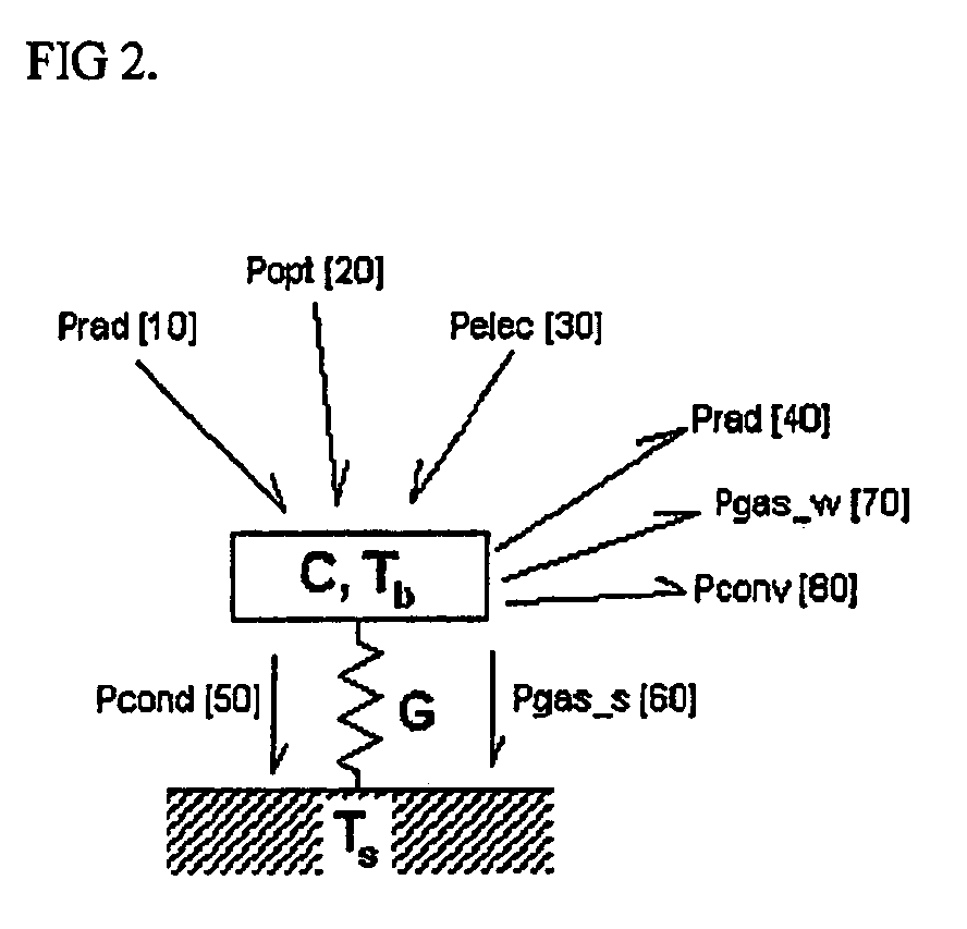
[0008]The method for sensing gas composition and gas pressure is based on the thermal constants of a variable electrical resistor. The method consists of monitoring the variable electrical resistor whose dynamic thermal response is determined by the thermal conductivity and thermal capacity of the surrounding gas of a given atmospheric environment. The gas sensor and method of operation herein described in this invention disclosure comprises a variable electrical resistor and a readout circuit for driving the electrical voltage across the variable resistor. When the variable resistor is electrically excited and heated by the readout circuit, its temperature at equilibrium is a function of applied electrical power and of thermal transf

Problems solved by technology

However, existing MEMS micro-sensor devices may show inaccurate pressure readings when subjected to temperature fluctuations, especially at low pressures.
Furthermore, the method for pressure measurement relies on an absolute voltage reading instead of differential voltage readings, wherein absolute voltage reading may be subjected to inaccuracies if fabrication errors occur from one sensor to the other.
The method described in this prior art does not provide gas composition measurements.
However, temperature compensation of the gauges is achieved at the cost of structural complexity of the device and readout circuit, which impede integration of such sensors into MEMS micro-devices.
Furthermore, the method for pressure measurement relies on an absolute voltage reading instead of differential voltage readings which lead to inaccuracies if fabrication errors occur from one gauge to the other.
The methods described in these prior arts do not provide gas composition measurements.
This disclosure relates to an apparatus comprising a vacuum container, a pressure container, a discharge container, an ion gauge and a residual gas analyzer; arranged in such a way that miniaturization becomes very difficult and integration to standard CMOS processes and to MEMS micro-device is not achievable in practice.

Method used


Image

  • Method for sensing gas composition and pressure
  • Method for sensing gas composition and pressure
  • Method for sensing gas composition and pressure

Examples


Embodiment Construction

[0026]The invention presents a novel method for measuring gas composition or gas pressure of a given atmospheric environment. The gas sensor and method of operation herein described in this invention disclosure provides real-time gas composition or gas pressure measurements over a large dynamic range. The gas sensor and method of operation are compatible to standard CMOS fabrication processes and readout circuits.

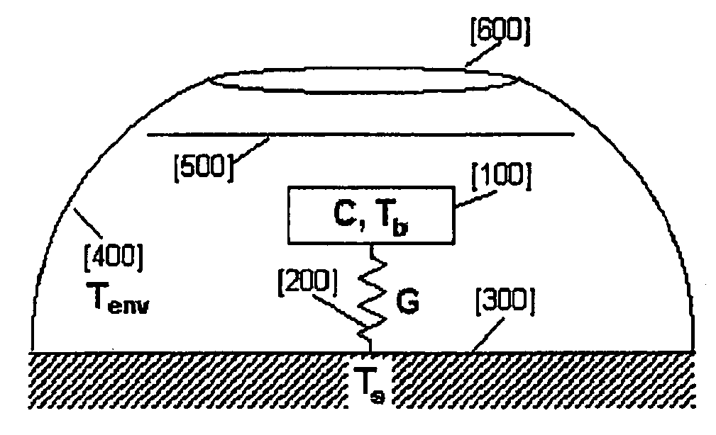
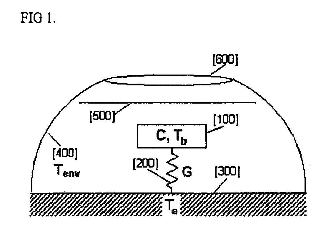
[0027]FIG. 1 schematizes an exemplary embodiment of the gas sensor. The gas pressure sensing element consists of a variable electrical resistor [100], whose electrical resistance changes with respect to a change of its temperature. The variable electrical resistor [100] is suspended in close proximity to a substrate [300] through suspending legs [200]. The variable electrical resistor [100] may consist of a suspended micro-thermistor, a suspended micro-electro-mechanical (MEMS) element, a suspended micro-bolometer platform, a suspended micro-wire, a suspended coil, or any v...


PUM


Abstract

A method for sensing gas composition and gas pressure, based on the thermal constants of a variable electrical resistor, is presented. The method for sensing gas composition and pressure includes monitoring a variable electrical resistor whose dynamic thermal response is determined by the thermal conductivity and thermal capacity of the surrounding gas of a given atmospheric environment. In the thermal domain, the sensor has a low-pass characteristic, whose phase delay is determined by the thermodynamic characteristics of the surrounding gas such as composition and pressure. The method can be used for sensing gas composition and can also be used for sensing gas pressure.

Description

FIELD OF THE INVENTION[0001]The present invention is directed to a method and apparatus for sensing gas composition or pressure or both.BACKGROUND OF THE INVENTION[0002]A conventional sensor, such as a Pirani gauge, is calibrated against several known pressures to determine a relationship between ambient pressure and power dissipated by the sensor. On one hand, since a Pirani gauge may be designed to have a wide dynamic range and be relatively simple and inexpensive, there is a need to be able to use this type of pressure gauge as a substitute for much higher priced gauges such as capacitance manometers and ionization gauges. On a second hand, the growing markets of high-performance wafer-level micro-packaging require miniaturization of the pressure sensors and integration to standard CMOS processes and MEMS micro-devices such as bolometers, gyroscopes and accelerometers. In addition, these markets may require the capability of the sensor for measuring both the gas composition and t...

Claims


Application Information

Patent Timeline
IPC IPC(8): G01N25/18G01N7/00
CPCG01N27/18
Inventor VIENS, JEAN FRANCOISLE NOC, LOIC
Owner INSTITUT NATIONAL D'OPTIQUE
Learn More