
Systems and methods for operating a two-dimensional transducer array

Active Publication Date: 2010-06-17
GENERAL ELECTRIC CO
View PDF29 Cites 82 Cited by
  • Summary
  • Abstract
  • Description
  • Claims
  • Application Information

AI Technical Summary

Benefits of technology

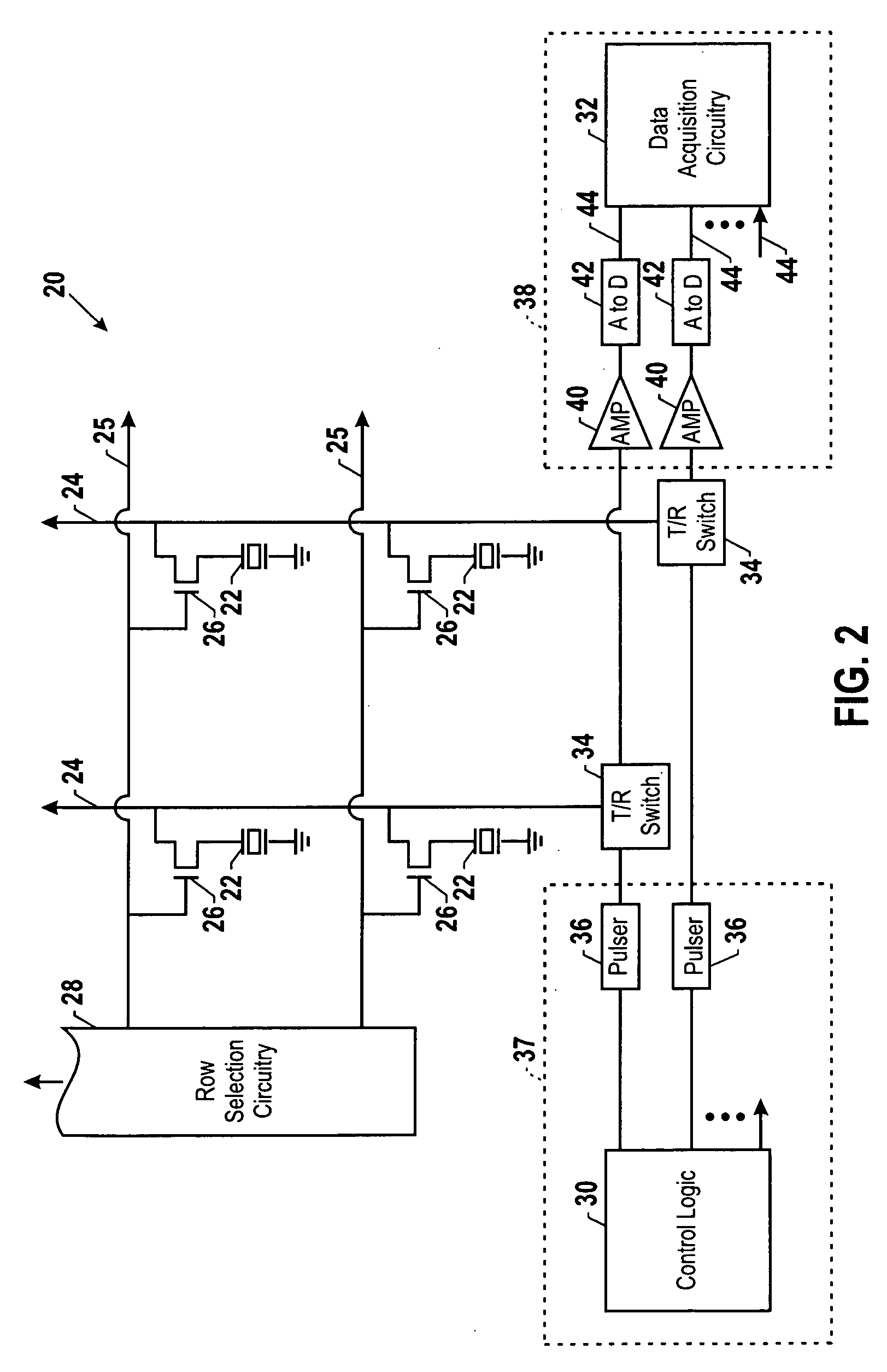
[0005]According to embodiments of the present technique, a system and a method for addressing transducers in a two-dimensional array is disclosed. According to one aspect of the present technique, the transducers are arranged in rows and columns, and the columns are coupled to shared transmit and receive circuitry while the rows are coupled to row selection circuitry. In another embodiment, each transducer is coupled to separate, dedicated transmit circuitry and the columns are coupled to shared receive circuitry. In both embodiments, the number of individual electrical interconnects used to communicatively couple the transducers to the signal generating and receiving circuitry is reduced.

Problems solved by technology

The technical difficulty and expense of fabricating a large number of electrical connections may limit the number of transducers that may be included in a typical transducer array.

Method used


Image

  • Systems and methods for operating a two-dimensional transducer array
  • Systems and methods for operating a two-dimensional transducer array
  • Systems and methods for operating a two-dimensional transducer array

Examples


Embodiment Construction

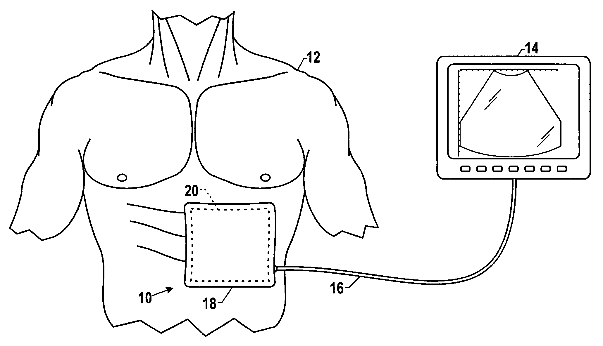
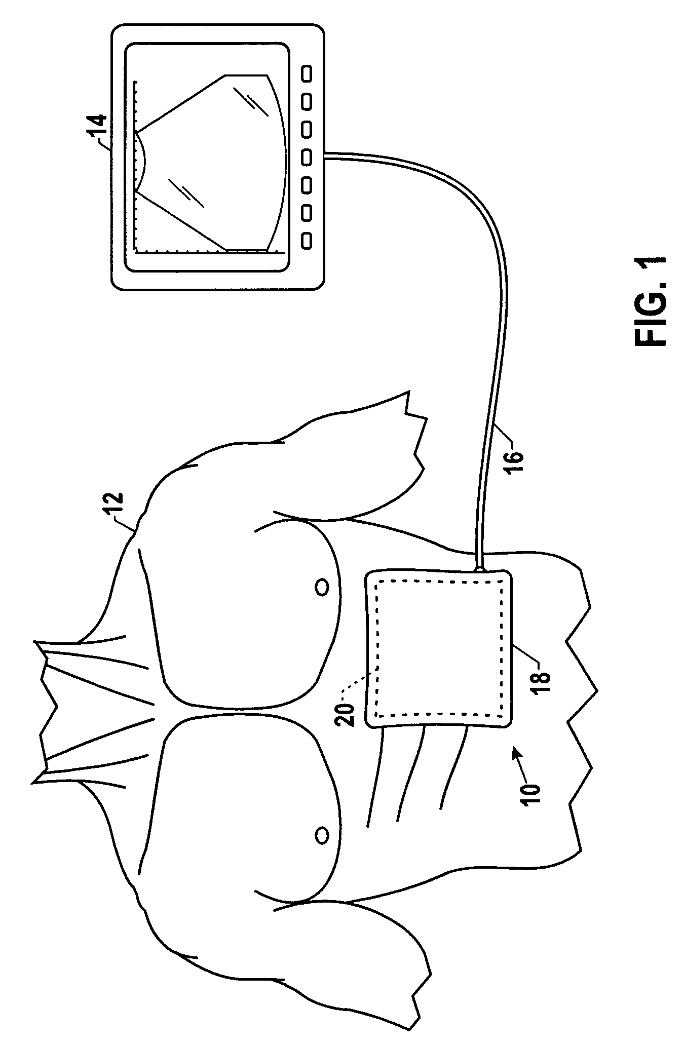
[0013]The techniques disclosed herein enable a transducer array to be fabricated without the use of individual dedicated processing electronics for each transducer. In accordance with embodiments disclosed herein, a two dimensional transducer array may be fabricated that uses a plurality of signal busses, each of which may be shared by several transducers. To enable activation of individual transducers, the transducers may be coupled to the signal bus through a switch that is activated by selection circuitry. By providing techniques of addressing transducers in an array that is less technically challenging and more economical, transducer arrays may be fabricated that are much larger compared to existing ultrasound technology, enabling new ultrasound techniques and devices with large two-dimensional transducer arrays.

[0014]FIG. 1 is an exemplary ultrasound device that includes a large two-dimensional transducer array with improved techniques for addressing the transducers in accordan...


PUM


Abstract

According to embodiments of the present technique, a system and a method for addressing transducers in a two-dimensional transducer array is disclosed. According to one aspect of the present technique, the transducers are arranged in rows and columns, and the columns are coupled to a shared transmit and receive circuitry while the rows are coupled to a row selection circuitry. In another embodiment, each transducer is coupled to a separate, dedicated transmit circuitry and the columns are coupled to a shared receive circuitry.

Description

BACKGROUND[0001]The invention relates generally to two-dimensional transducer arrays. In particular, the invention relates to techniques for addressing individual transducer elements within a two-dimensional transducer array.[0002]A medical ultrasound imaging system forms an image by transmitting an acoustic wave into a subject and receiving and processing the reflected acoustic waves. Typically, a plurality of ultrasonic transducers both send the transmitted wave and receive the reflected waves. Such scanning comprises a series of measurements in which the ultrasonic wave is transmitted, the system switches to receive mode after a short time interval, and the reflected ultrasonic wave is received, beamformed, and processed for display.[0003]The transducer elements are typically driven individually by an input voltage waveform. By implementing time delays and amplitude differences between the input waveforms, the individual transducer elements can be controlled to produce ultrasonic...

Claims


Application Information

Patent Timeline
IPC IPC(8): A61B8/00
CPCA61B8/00G01S15/8925A61B8/4483A61B8/4281
Inventor HAIDER, BRUNO HANSLEWANDOWSKI, ROBERT STEPHENWODNICKI, ROBERT GIDEON
Owner GENERAL ELECTRIC CO
Learn More