Negative electrode for coin-shaped lithium secondary battery, method for producing the same, and coin-shaped lithium secondary battery
a lithium secondary battery, coin-shaped technology, applied in the direction of electrochemical generators, cell components, cell component details, etc., can solve the problems of not being practical, not being able to expect a drastic capacity increase of the whole negative electrode, and difficulty in maintaining the structure of the negative electrode, etc., to achieve easy maintenance of the negative electrode structure, improve the followability to volume change, and facilitate the effect of ensuring
- Summary
- Abstract
- Description
- Claims
- Application Information
AI Technical Summary
Benefits of technology
Problems solved by technology
Method used
Image
Examples
example 1
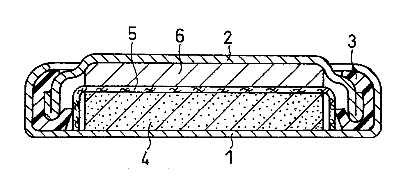
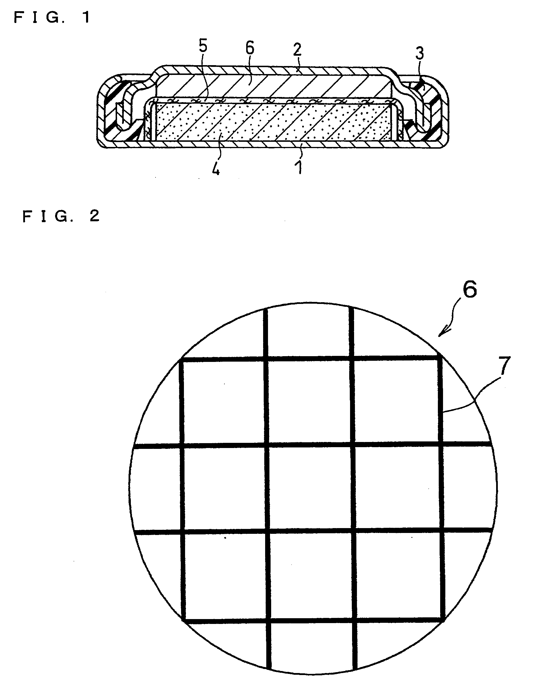
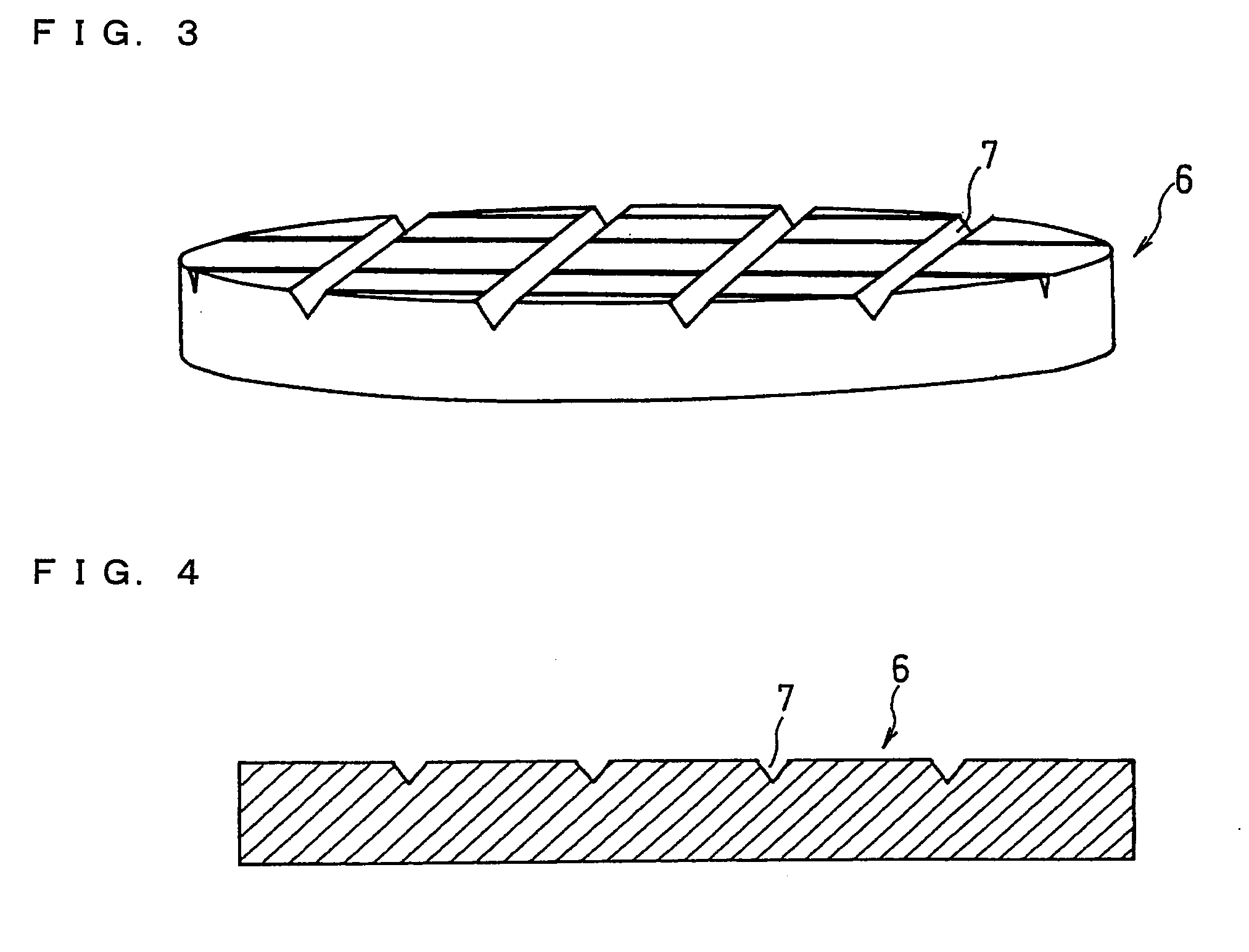
[0091]A coin-shaped lithium secondary battery as shown in FIG. 1 was produced.
(i) Synthesis of Positive Electrode Active Material
[0092]Manganese dioxide and lithium hydroxide were mixed together in a molar ratio of 2:1, and the mixture was baked in air at 400° C. for 12 hours to obtain lithium manganate. This was used as a positive electrode active material.
(ii) Positive Electrode Preparation
[0093]The lithium manganate as the positive electrode active material, acetylene black as a conductive agent and an aqueous dispersion of polytetrafluoroethylene as a binder were mixed together in a weight ratio of 88:6:6 in terms of the solid contents, to obtain a positive electrode material mixture. The positive electrode material mixture was molded into a coin-shaped pellet of 4 mm in diameter and 1.0 mm in thickness, and the pellet thus obtained was dried at 250° C. for 12 hours to prepare a molded positive electrode 4.
(iii) Synthesis of Negative Electrode Active Material
[0094]As the negativ...
example 2
[0107]A battery A2 was produced in the same manner as in Example 1 except that the flat face having the recessed portions of the molded negative electrode 6 was placed so as to face the separator (the under side in FIG. 1).
example 3
[0108]When the molded negative electrode was prepared, the same lattice-shaped raised portions as those on the one mold were formed on the surface of the other mold, and thus lattice-shaped recessed portions having a spacing of 0.8 mm were formed on the both flat faces of the molded negative electrode. However, as shown in FIGS. 8 and 9, the recessed portions of the one flat face and the recessed portions of the other flat face were relatively displaced so that the recessed portions of the one flat face might not be opposite to those of the other flat face. A battery A3 was produced in the same manner as in Example 1 except that the molded negative electrode thus prepared was used.
PUM
| Property | Measurement | Unit |
|---|---|---|
| crystallite size | aaaaa | aaaaa |
| thickness | aaaaa | aaaaa |
| thickness | aaaaa | aaaaa |
Abstract
Description
Claims
Application Information
 - R&D
- Intellectual Property
- Life Sciences
- Materials
- Tech Scout
- Unparalleled Data Quality
- Higher Quality Content
- 60% Fewer Hallucinations
Browse by: Latest US Patents, China's latest patents, Technical Efficacy Thesaurus, Application Domain, Technology Topic, Popular Technical Reports.
© 2025 PatSnap. All rights reserved.Legal|Privacy policy|Modern Slavery Act Transparency Statement|Sitemap|About US| Contact US: help@patsnap.com


