
Radiation CT imaging apparatus

Inactive Publication Date: 2010-06-17
FUJIFILM CORP
View PDF5 Cites 9 Cited by
  • Summary
  • Abstract
  • Description
  • Claims
  • Application Information

AI Technical Summary

Benefits of technology

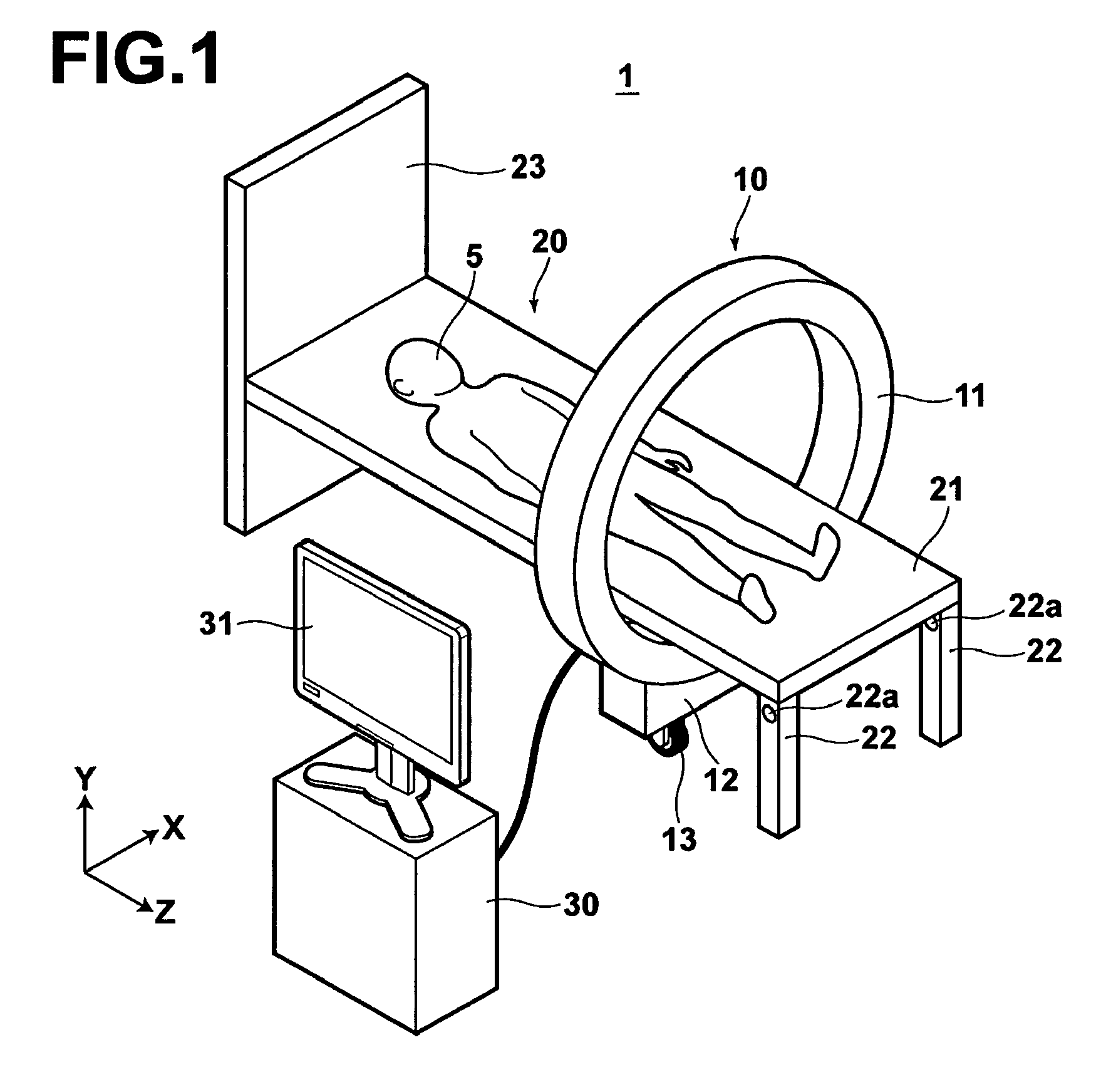
[0021]According to the first radiation CT imaging apparatus of the present invention, a plurality of radiation sources and a plurality of radiation detectors are integrated into a main imaging unit, and a moving member is provided to the main imaging unit. This allows a downsized main imaging unit, which does not require a rotation mechanism, to be realized and the portability is improved.
[0022]In the first radiation CT imaging apparatus, if the main imaging unit is formed in a cylindrical shape, and the leg of the mounting board is configured to be folded when the mounting table passes an inner cylinder side of the cylindrically shaped main imaging unit and the mounting board is configured to be placed on an inner cylindrical surface, the main imaging unit may be set to the mounting table more smoothly.
[0023]Further, if a rotatable rolling member for holding the mounting board is provided on the lower surface of the mounting board or on the inner cylinder surface of the main imaging unit, the main imaging unit may be moved smoothly when imaging is performed by moving the main imaging unit.
[0024]Still further, if a rotatable rolling member for holding the mounting board is provided on the inner cylinder surface of the main imaging unit, and a groove for fittingly receiving the rolling member is formed in the lower side of the mounting board running in the longitudinal direction of the board, or if a floor groove for fittingly receiving the moving member is formed in a floor, on which the mounting table is installed, running in the longitudinal direction of the mounting board, the main imaging unit may be moved more smoothly and without positional displacement with respect to the subject placed on the mounting table when imaging is performed by moving the main imaging unit.
[0025]Further, if the mounting board is formed of a material having a low absorption rate for radiation, absorption of the radiation by the mounting board may be reduced and, for example, a metal artifact may be prevented.
[0026]According to the second radiation CT imaging apparatus of the present invention, the plurality of radiation sources and the plurality of radiation detectors are integrated into a main imaging unit, and an arm member, having a first end connected to the main imaging unit and a second end to be movably held, and a rail for movably holding the arm member are further provided. This allows a downsized main imaging unit, which does not require a rotation mechanism, to be realized and the portability is improved.

Problems solved by technology

X-ray imaging with a conventional portable X-ray machine, however, can not provide sufficient observation information for a patient under intensive care or after operation, and it has been awaited for an apparatus capable of obtaining an image having sufficient observation information, such as a radiation CT image.
The radiation CT imaging apparatus described in U.S. Pat. No. 7,570,734, however, has a large size because of a rotation mechanism for rotating the C-arm gantry and it is very inconvenient to bring inside a room.
Further, the C-arm gantry is rotated by the rotation mechanism so that a positional displacement may occur in the gantry which needs to be corrected, whereby the apparatus becomes complicated and increased cost.

Method used


Image

  • Radiation CT imaging apparatus
  • Radiation CT imaging apparatus
  • Radiation CT imaging apparatus

Examples


first embodiment

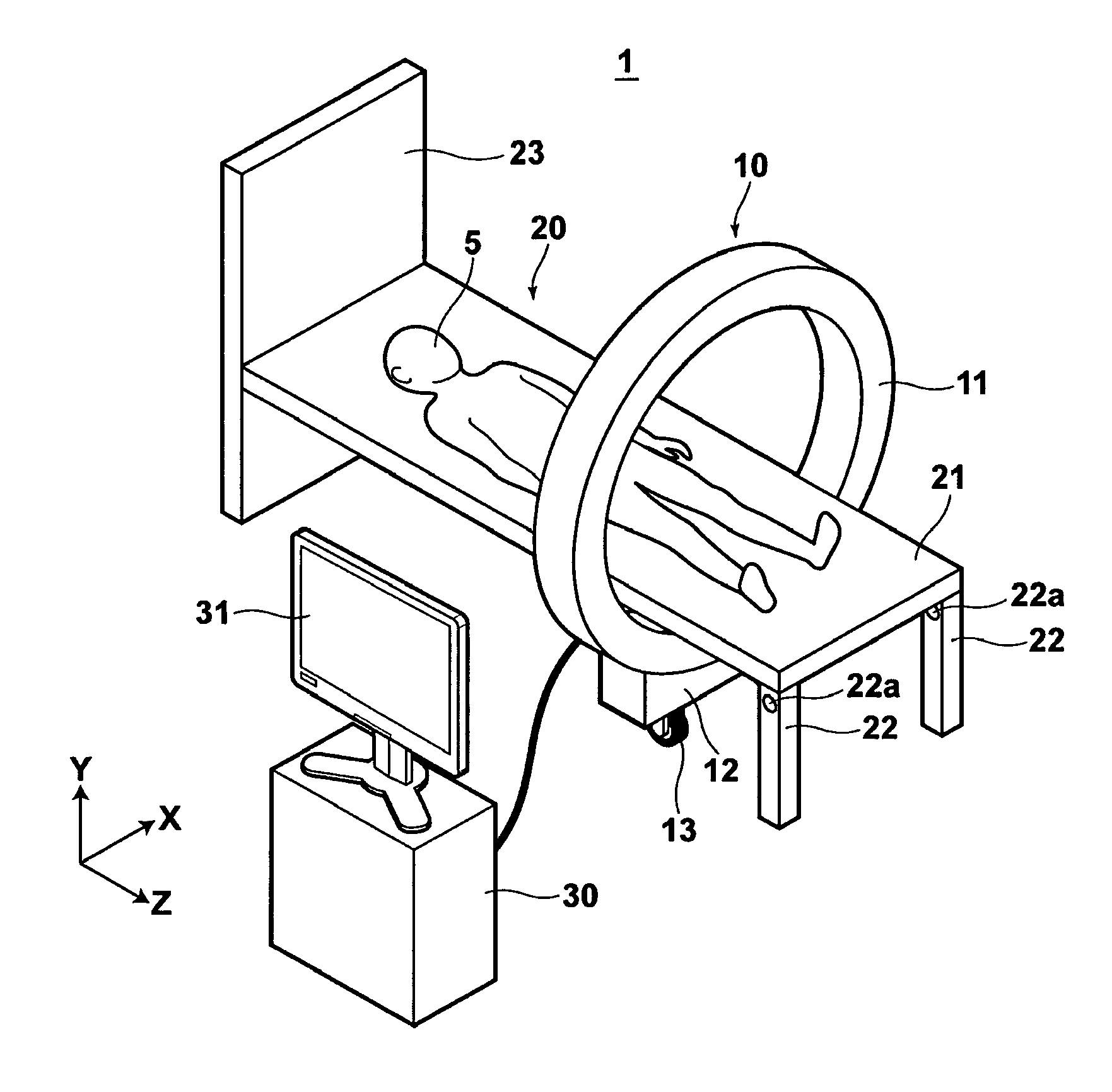
[0037]Hereinafter, the radiation CT imaging apparatus of the present invention will be described with reference to the accompanying drawings. FIG. 1 is a perspective view of radiation CT imaging apparatus 1, illustrating a schematic configuration thereof.

[0038]As shown in FIG. 1, radiation CT imaging apparatus 1 includes portable imaging unit 10 having fixed gantry 11 in which a plurality of radiation sources for emitting radiation and a plurality of radiation detectors for detecting radiation transmitted through subject 5 are integrally provided, mounting table 20 on which subject 5 is placed, and image signal processing unit 30 that generates and displays a tomographic image of subject 5 based on radiation image signals detected by the radiation image detectors of portable imaging unit 10.

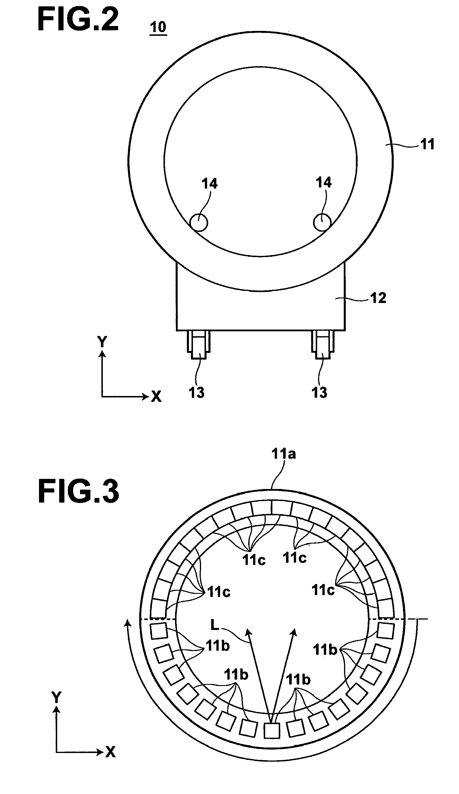
[0039]FIG. 2 is an X-Y plan view of portable imaging unit 10. As shown in FIGS. 1 and 2, portable imaging unit 10 includes fixed gantry 11 having a plurality of radiation sources and radiation de...

second embodiment

[0060]the radiation CT imaging apparatus of the present invention will now be described.

[0061]In radiation CT imaging apparatus 1 of the first embodiment, fixed gantry 11 is made movable by equipping portable imaging unit 10 with casters 13. While in radiation CT imaging apparatus 2 of the second embodiment, fixed gantry 51 is made movable by equipping fixed gantry 51 of main imaging unit 50 with arm members 52 and moving the arm members 52, as illustrated in FIG. 9.

[0062]More specifically, each arm member 52 is connected to fixed gantry 51 at one end and movably held by rail 3a at the other end. Rails 3a are provided on the ceiling of a room where mounting table 20 is installed running in the longitudinal direction of mounting table 20.

[0063]In radiation CT imaging apparatus 2 of the second embodiment, fixed gantry 51 is moved in the longitudinal direction of mounting table 20 by moving arm members 52 along rails 3a provided on ceiling 3.

[0064]Then, as in the radiation CT imaging a...


PUM


Abstract

A plurality of radiation sources and a plurality of radiation detectors are integrated into a main imaging unit and a moving member is provided to the main imaging unit.

Description

BACKGROUND OF THE INVENTION[0001]1. Field of the Invention[0002]The present invention relates to a radiation CT imaging apparatus for obtaining a tomographic image of a subject.[0003]2. Description of the Related Art[0004]It has been practiced to take an X-ray image with a portable X-ray machine at a bedside of a seriously ill hospital patient who is unable to move to a radiography room for follow-up observations.[0005]X-ray imaging with a conventional portable X-ray machine, however, can not provide sufficient observation information for a patient under intensive care or after operation, and it has been awaited for an apparatus capable of obtaining an image having sufficient observation information, such as a radiation CT image.[0006]Consequently, for example, U.S. Pat. No. 7,570,734 proposes a portable radiation CT imaging apparatus having a C-arm gantry with a horizontal rotating shaft.[0007]The radiation CT imaging apparatus described in U.S. Pat. No. 7,570,734, however, has a l...

Claims


Application Information

Patent Timeline
IPC IPC(8): H05G1/60H05G1/02
CPCA61B6/032A61B6/04A61B6/035
Inventor KAWAMURA, TAKAHIRO
Owner FUJIFILM CORP
Learn More