
Organic electroluminescence device

a technology of electroluminescence and organic materials, applied in the direction of luminescnet screens of discharge tubes, organic chemistry, natural mineral layered products, etc., can solve the problems of low luminance, inconvenient dopants, and prevented efficient injection and transport of charge carriers into the light-emitting layer, etc., to achieve narrow emission band, significant efficiency drop, and high efficiency

Active Publication Date: 2010-06-17
CITY UNIVERSITY OF HONG KONG
View PDF15 Cites 17 Cited by
  • Summary
  • Abstract
  • Description
  • Claims
  • Application Information

AI Technical Summary

Benefits of technology

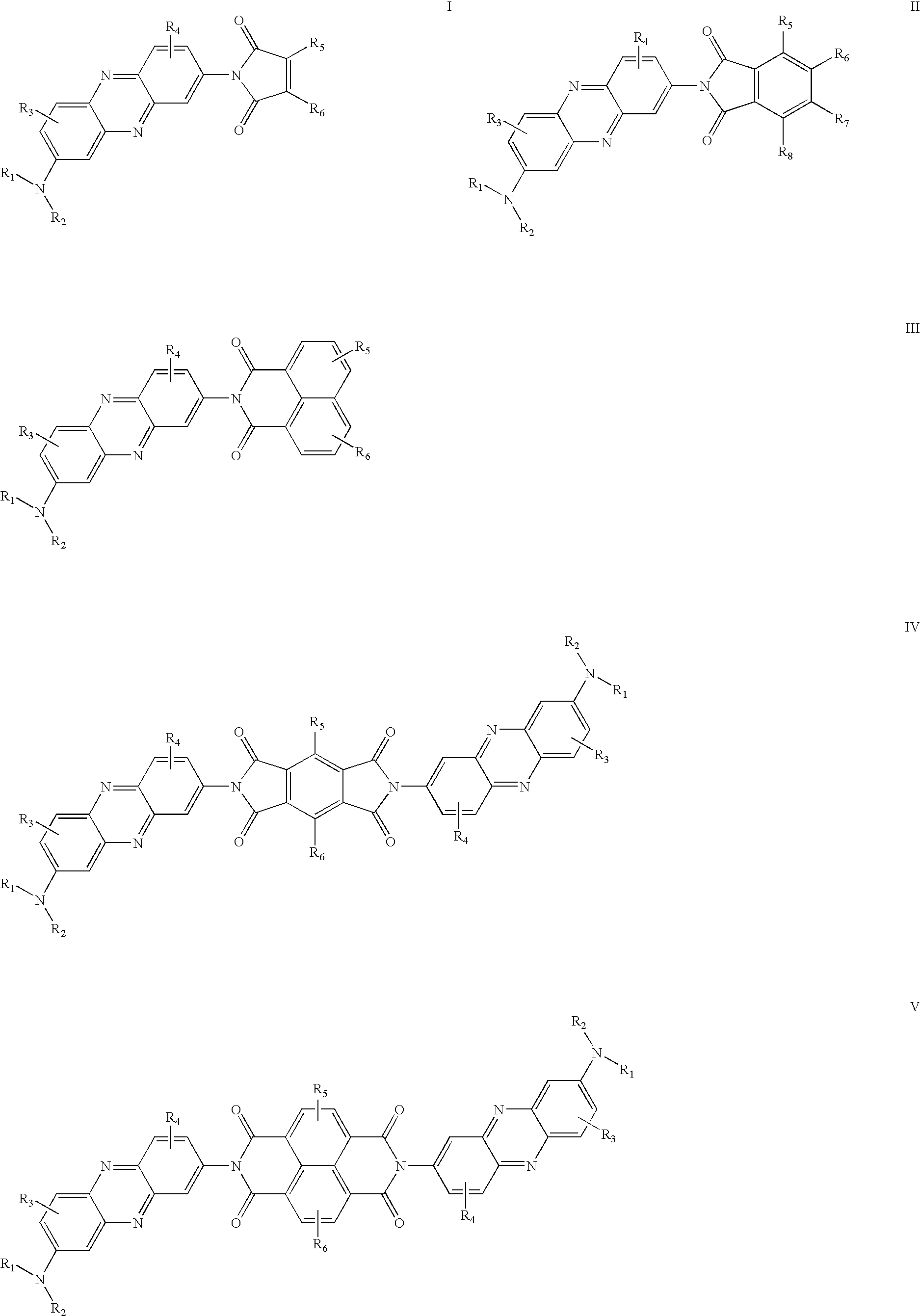
[0008]In the current invention Neutral red and its derivatives are used as the guest material of dopant. Neutral red and its derivatives are a kind of the phenazine dyes. Most neutral red derivatives are strongly fluorescent in longer wavelengths such as the orange-red region. The neutral red derivatives in the present invention are typical ICT compounds, so these compounds are expected to have the general features of ICT compounds mentioned above. Moreover, they have an additional feature of high fluorescence and have a narrow emission band due to the totally rigid structure between the donor and accepter resulting in an organic EL device with improved efficiency and high brightness.
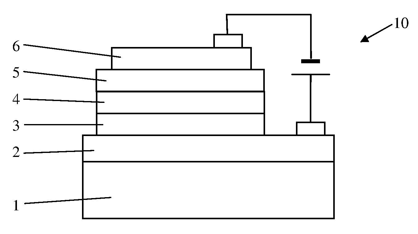
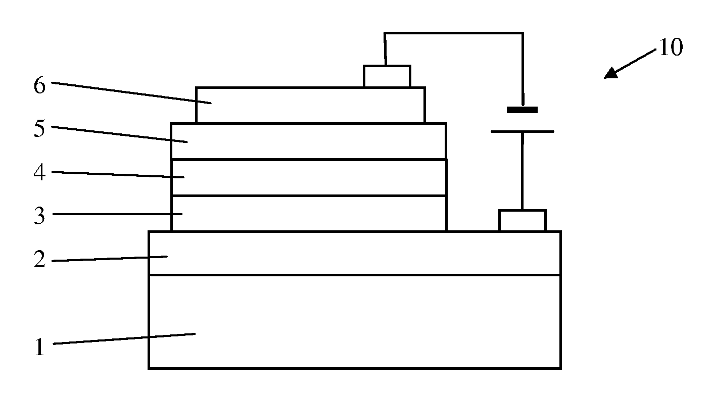
[0012]An organic EL device of the invention has high efficiency and narrow emission band. For example, when one derivative is doped into Alq3, it gives a very bright yellow, orange to red emission depending on the doping concentrations. The device with a doping concentration 1% (wt %) exhibited a maximum brightness of 21800 cd / m2 at a driving voltage of 12 V, and the current efficiency is 6.2 cd / A at a current density of 20 mA / cm2; a orange emission from the doped emitting material with maximum wavelength 586 nm, and an red emission at high doping concentrations with maximum wavelength 612 nm. In particular, the device shows that the current efficiencies remain almost flat for a wide range of current density from 1 mA / cm2 to 500 mA / cm2 at different doping concentrations. The current devices show obvious advantages over many reported red-emitting OLEDs which show significant drops in efficiency as increasing current density and / or dopant concentration. The present dopant is particularly suitable for the passive-matrix displays application where a high excitation density is required. Furthermore, the materials provided by the invention are easy to prepare, and thus are economically attractive.

Problems solved by technology

The reason for the low luminance of early organic EL devices was the highly resistive EL medium, which prevented the efficient injection and transport of charge carriers into the light-emitting layer.
Since the fused homo-aromatic compounds with a large conjugated structure, especially those that emit in red, are often oxidized easily by singlet oxygen in ambient conditions they are not suitable dopants unless the EL devices are used in the dark or without oxygen.
(iii) Their Stokes shifts are generally large to prevent efficient self-re-absorption, especially in the solid state.

Method used


Image

  • Organic electroluminescence device
  • Organic electroluminescence device
  • Organic electroluminescence device

Examples


example 1

Synthesis of Neutral Red Derivative Compound 1

[0030]0.25 g Neutral red and 0.2 g 4-chloro-1,8-naphthalic anhydride were suspended in 20 ml quinoline. The mixture was refluxed for 24 hrs. at 220° C. under nitrogen. After cooling, the solution was poured into 50 ml ethanol. A red precipitate was collected, purified by recrystalization from ethanol; after dryness, 0.32 g deep red needles were obtained. 1HNMR (300 MHz, CDCl3) δ [ppm]: 2.43 (s, 3H), 3.23 (s, 6H), 7.07 (d, J=3.0 Hz, 1H), 7.62-7.65 (m, 1H), 7.83-7.88 (m, 2H), 8.01-8.15 (m, 2H), 8.33-8.36 (m, 2H), 8.71-8.74 (m, 2H); Anal. Calcd. For C27H19 Cl N4O2: C, 69.45; H, 4.10; N, 12.00%. Found: C, 69.63; H, 4.35; N, 12.19%; MS: m / z 467 (M++1).

[0031]Table 1 lists the absorption and emission maxima and fluorescence quantum yields of compound 1 in a variety of solvents. A red shift in the absorption and emission maxima was observed with increasing solvent polarity. The fluorescence quantum yield of compound 1 reveals a significant depen...

example 2

Synthesis of Neutral Red Derivative Compound 2

[0032]0.35 g Neutral red and 0.1 g 1,2,4,5-benzenetetracarboxylic anhydride were suspended in 20 ml quinoline. The mixture was refluxed for 48 hrs. at 220° C. under nitrogen. After cooling, the solution was poured into 50 ml ethanol. A red precipitate was collected, purified by re-crystallization from ethanol; after dryness, 0.18 g deep red solid were obtained. Anal. Calcd. For C40H30N8O4: C, 69.96; H, 4.40; N, 16.32%. Found: C, 69.86; H, 4.56; N, 16.59%; MS: m / z 687 (M++1).

example 3

Synthesis of Neutral Red Derivative Compound 3

[0033]0.25 g Neutral red and 0.1 g Naphthalene-1,4,5,8-tetracarbolxylic dianhydride were suspended in 20 ml quinoline. The mixture was refluxed for 48 hrs. at 220° C. under nitrogen. After cooling, the solution was poured into 50 ml ethanol. A red precipitate was collected, purified by recrystalization from ethanol; after dryness, 0.22 g black red solid were obtained. Anal. Calcd. For C44H32N8O4: C, 71.73; H, 4.38; N, 15.21%. Found: C, 71.83; H, 4.65; N, 15.59%; MS: m / z 737 (M++1).

[0034]Electroluminescence Device Fabrication

[0035]The detailed results of electroluminescence (EL) are indicated in the following specific examples of the present invention. It is evident that the EL devices shows very bright orange to red emission with high efficiencies and relatively narrow emission band, and the current efficiencies of EL devices remain almost unchanged in a wide range of drive current density up to 500 mA at different doping concentrations,...


PUM

PropertyMeasurementUnit
current densityaaaaaaaaaa
brightnessaaaaaaaaaa
current efficiencyaaaaaaaaaa

Abstract

An electroluminescence device has an anode, a cathode and an emitting layer located between the anode and the cathode. The emitting layer contains a compound selected from a group consisting of neutral red and its derivatives.

Description

FIELD OF THE INVENTION [0001]This invention relates to organic electroluminescence (EL) devices.BACKGROUND OF THE INVENTION [0002]U.S. Pat. Nos. 3,172,862, and 3,173,050 both granted in the 1965 teach the preparation of an organic electroluminescence (EL) device using conjugated materials generally having a fused aromatic ring. The efficiency and life of such organic EL devices was much lower than those obtained from inorganic systems. Therefore, research at that time was mainly focused on inorganic materials. The reason for the low luminance of early organic EL devices was the highly resistive EL medium, which prevented the efficient injection and transport of charge carriers into the light-emitting layer. Tang and VanSlyke (Tang and VanSlyke, Appl. Phys. Lett. 1987, 51, 913) solved this problem successfully in the late 1980s by using a structure made of two ultra thin layers: a hole transporting layer of an organic substance laminated on an organic emitting layer. This work revive...

Claims


Application Information

Patent Timeline
Patent Type & Authority Applications(United States)
IPC IPC(8): H01J1/63C07D235/02
CPCC07D241/46C07D401/04H05B33/14C09K2211/1029C09K2211/1044C09K11/06
Inventor LEE, SHUIT-TONGLEE, CHUN SINGWANG, PENGFEIXIE, ZHIYUAN
Owner CITY UNIVERSITY OF HONG KONG
Learn More